This is a guide to using g-code command M206 to set the Z axis home offset in the Marlin Firmware, a guide to a method of adjusting the gap distance between the hot end nozzle and the build platform. To set the Z axis home offset on the 3d printer, you will use g-code commands including M206 for the home offset, M500 and M501 for the Marlin Firmware EEPROM feature, and G1 for controlled move to Z axis zero position.
Set Gap Between Nozzle And Bed Using G-Code, EEPROM & Marlin Firmware
About
Firstly, this guide may not be suitable for all 3d printers, probably those printers that are the delta type and those with the auto bed levelling feature. Apart from that, for this guide to work for you, you will need a 3d printer configured with a Z+ end stop.
On a lot of 3d printer set-ups, the gap between the nozzle tip and the build platform surface is just a fraction of a millimetre, so it does not take much to upset the gap distance. Things like levelling the build platform, changing the hot end nozzle and using different filament types can cause the first layer height to be out of calibration.
Usually, as accurately as possible, you would only adjust the final travel limit for Z axis in the Marlin Firmware, then upload the firmware to the controller motherboard. However, if adjustments are going to be made more often, it would be more convenient to adjust the final travel limit using the home offset feature.
The guide will explain a method of applying an offset to the Z axis to extend the maximum travel limit, initially set in the Marlin Firmware, using Pronterface. A combination of g-codes will be used through Pronterface so that the home offset can be set, saved and tested. An initial edit in the Marlin Firmware configuration.h file is required, but beyond that, you would only need to change the home offset value to change the gap distance between the hot end nozzle and the 3d printer build platform.
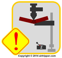
3D Printer Axis Crash Caution – Axis crash is possible with manual jog when software end-stops are disabled
Removed Safeguards – Important
This guide, an extension to the Marlin Firmware v1, Basic Configuration Set-up Guide, covers editing the Marlin Firmware configuration.h file to enable EEPROM support and to disable software end-stops, and as a result of editing the configuration file, it will be important to note that some operational safeguards will be disabled; it will be possible to manually jog an axis beyond its travel limits, probably resulting in an axis crash and possibly causing damage. Accidentally pressing the 100mm jog button instead of the 10mm jog button, is an example of what could cause a 3d printer axis crash; this would normally be prevented by enabled software end-stops. Attempting to print models outside the physical print area could also cause an axis crash also.
Only use this method to set home offset, as described in this guide, if the users of your 3d printer are aware of the manual jog limits and the risk of crashing an axis when exceeding the limits. It would be recommended to include axis homing to the g-code compiler start file so that homing is automatically applied to the model g-code files at compile time. It would be good practice to manually home the 3d printer, using the printer interface such as Cura or a printer control interface, before starting each print.
Marlin Firmware Configuration
If you are attempting to configure the Marlin Firmware for the first time you will need to head over to the Marlin Firmware set-up guide here to get started with the basics.
It’s basically going to be a quick edit of the Configuration.h before we get started with the main guide to configuring the home offset. Use the Arduino IDE search tool to quickly find the lines of code needed for editing.
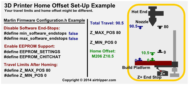
3D Printer Marlin Firmware & Home Offset Set-up Example
Disable Software End-Stops
To configure the home offset successfully, we’ll need to be able to travel beyond the fixed travel limits set in the Marlin Firmware. When software end-stops are enabled, the home offset will not work outside the axis travel limits. If we want the axis to travel to maximum position plus home offset, we will need to disable software end-stops.
#define min_software_endstops false
#define max_software_endstops false
Software end-stops are enabled by default. To disable software end-stops, find the above lines of code in Marlin Firmware Configuration.h file and set each line to false as shown.
Enable EEPROM Suport
After setting the Z axis home offset on the 3d printer, we want to store the setting in EEPROM so that the home offset value we want to use is available automatically when the printer is started.
#define EEPROM_SETTINGS
#define EEPROM_CHITCHAT
To enable EEPROM support in the Marlin Firmware, uncomment the above code snippets by removing the forward slashes at the start of each line of code.
Travel Limits After Homing
Ideally, we want to set a maximum travel limit that stops the hot end a good safe distance above the build platform with home offset set to zero, and then fill the gap between the nozzle and the build platform with home offset. If you change the build platform thickness by adding a glass surface for PLA and then remove glass surface for ABS, you will have to allow for the thickness of the glass also. A guide to clearing the current home off set is included further down this article.
#define Z_MAX_POS 80
Normally, you will only need to change the value for Z_MAX_POS; just edit the above line of code to the maximum travel limit you want to set for your 3d printer. On my 3d printer for example, I have around 90mm of travel on the Z axis, as shown in the above code, I’ve set the Z_MAX_POS to 80, that leaves around 10mm to play with when setting the home offset.
Marlin Firmware Home Offset Guide
Some Preparation
After the Marlin Firmware is configured as above, the build platform needs to be levelled before attempting to set the Z axis home offset. You will need to be prepared to fine tune the final offset measurement while the hot end and the heated build platform are up to working temperature. You can practice setting the home offset while the 3d printer is cold, this will avoid trial and error while the nozzle is hot and not extruding for long length of time.
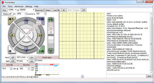
Pronterface – 3D Printer Interface Software
Setting home offset and storing to EEPROM is done through the 3d printer interface software such as Cura and Pronterface. Both Cura and Pronterface have a terminal interface that allow the user to send g-code commands to the Marlin Firmware. For this guide, Pronterface will be used because manual jog controls and terminal are in the same application window for convenience.
Terminal inputs may be case sensitive in some 3d printer software interfaces, if you get an error or no response in the terminal feedback window, check that you are typing upper-case g-code commands.
Setting & Testing Home Offset
Quick Brief
There are seven steps to follow in this guide, first two steps will be to check and clear existing offset for the Z axis, followed by five steps to set and test new home offset. If you are using the Marlin Firmware home offset feature for the first time, please be sure to read through the whole guide first before changing any settings.
The guide describes a set-up that is similar to my 3d printer only, so the Z axis measurements used in this guide are there as a set-up example and not meant to be copied for use in other 3d printer set-ups. If you’ve read the guide in full, you’ll have an idea of what measurements to use on your 3d printer to set your own home offset.
Checking & Clearing Existing Home Offset
Saving a new home offset setting will replace a previously saved offset in EEPROM, so if you’re using a 3d printer you’re not familiar with, avoid unexpected results by first checking for existing offset setting. The next two steps will help to discover and clear an existing offset.
Step 1. This is a simple check to see if an offset has been set.

Check Current Home Offset Setting Stored In EEPROM
- Not an essential step to clearing home offset, put the 3d printer in a safe position by homing each axis after powering up the printer.
- Enter the g-code M501 in the terminal interface text box.
- Press the send button to send the g-code to the 3d printer.
- Data stored in EEPROM is then read to the terminal window. Look for the line with M206 to find the current Z axis home offset.
Step 2. You can fine tune existing offset by jumping to later steps, or you can start a fresh by setting offset to Zero.
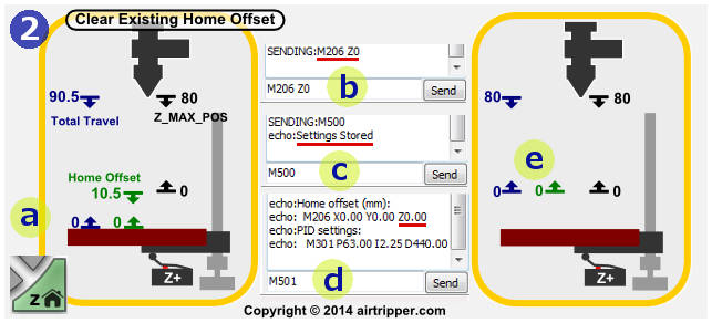
Step 2 – Clear Existing 3D Printer Z Axis Home Offset
- An illustration of what an existing home offset looks like, which can be compromised after build platform re-levelling.
- Clear the current Z axis home offset by sending g-code M206 Z0 through the terminal; we set the Z axis home offset to zero.
- Save the new home offset to EEPROM by sending g-code M500.
- Confirm that the new offset was saved to EEPROM by sending g-code M501.
- An illustration of what zero home offset looks like, the 3d printer should be homed after home offset changes.
Setting The Initial Home Offset – 3D Printer Cold
This part of the guide describes setting up an initial home offset while the printer is cold. Basically, we are setting a new offset that will be a centimetre or two short of what we need, we will get the hot end nozzle close to the build platform while the printer is cold. Then, later in this guide, we heat up the 3d printer for fine tuning the final offset.
Step 3. We prepare the printer for the next step so that an initial offset can be measured.
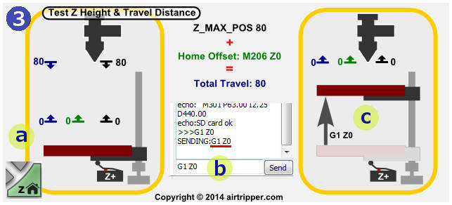
Step 3 – Test Z Axis Height & Z Travel Distance
- First, home the 3d printer. The illustration shows that Z_MAX_POS is much less than Z axis physical travel distance, this should give us room to set an offset.
- Send the Z axis to the zero position by sending g-code G1 Z0 through the 3d printer software interface terminal.
- The Z axis should now be positioned at zero. We are now ready to measure the initial offset in the next step.
Step 4. So, moving forward from Step 3. c, we are now going to set a rough home offset value with the 3d printer cold, no heaters switched on. If you are just fine tuning the final home offset value, you could probably skip to Step 5.
If you have a mirrored or glass build platform, slide a sheet of paper over the platform to avoid hot end nozzle reflection that can make you think the gap between the nozzle and platform is bigger than it actually is. If you prefer, centre X and Y axis over the build platform before measuring the gap between hot end nozzle and build platform.
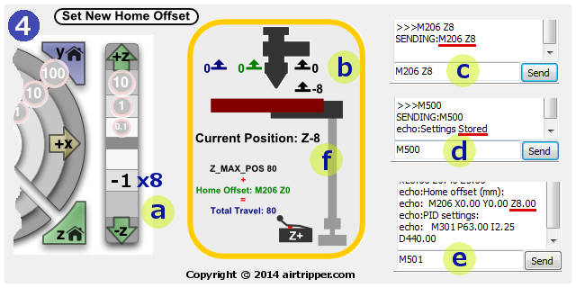
Step 4 – Set New Home Offset For Z Axis
- With the Z axis at zero position, as in Step 3. c, use the Z axis manual jog control to bring the hot end nozzle closer to the build platform in 1mm steps. Keep a count of how many 1mm steps, and stop when you get the nozzle about 1 to 2mm away from the platform. Make a note of the total of 1mm steps made for the home offset value. If fitted, the 3d printer LCD control interface will show Z as a negative number; this can be used as the home offset value, with the value changed to positive.
- The 3d printer build platform and nozzle is about a millimetre or two apart and we now know the initial offset value we want to start with. For my 3d printer, the initial home offset will be 8mm; because I allowed about 10mm for home offset when setting Z_MAX_POS in the Marlin firmware.
- We save the initial offset value to EEPROM, send the new offset value, using the g-code command M206 Z8, through the terminal; setting 8mm as the new home offset.
- Immediately save the new offset to EEPROM by sending the g-code M500.
- Check that the new offset was saved to EEPROM by sending g-code M501. Look for the line with M206 in it.
- With the offset now added and saved to EEPROM, -8 position becomes the new zero position, giving the Z axis a total of 88mm of travel, as the case with my 3d printer. The offset will be updated after homing the Z axis, in the next step.
Step 5. A new home offset value has been saved to EEPROM, and confirmed. Now it’s time to mechanically test the new offset before moving on to fine tuning. The 3d printer is still cold at this point, however, the build platform can be preheated now if preferred, especially if the platform takes a long time to heat up.
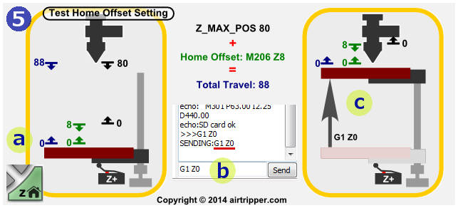
Step 5 – Test New Home Offset Setting
- To avoid disturbing the X and Y axis centred over the build platform, using the 3d printer software jog controls, home only the Z axis. When the Z axis is at the end stop, the gap between the hot end nozzle and the platform should be slightly more than both Z_MAX_POS and home offset added together.
- If the measurements check out as above, then it should be safe to send the Z axis to zero position, send the g-code command G1 Z0 through the terminal.
- The 3d printer Z axis should now be at zero position, leaving a millimetre or two gap between the hot end nozzle the the build platform as expected.
Fine Tuning The Initial Home Offset – 3D Printer Hot
Step 6. If you are jumping straight into fine tuning, you need to start from step 5. Right, we’re on to fine tuning the home offset now. This is were you need to be careful, because it is recommended to have the hot end and the build platform at working temperatures while setting the first layer height or gap between the nozzle and platform.
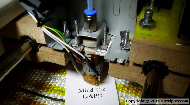
I use A4 photocopy or printer paper as a gap feeler for setting the gap between the nozzle and the platform. You may need to cut the A4 sheet to fit inside the printer, but have the sheet at a size so that it can be handled and positioned while avoiding hands and fingers touching the hottest parts of the 3d printer.
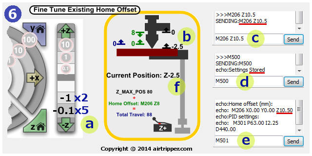
Step 6 – Fine Tune Existing Home Offset Setting
- Use the -Z axis jog control to fine tune the ideal offset, get the nozzle close enough to the platform to lightly grab the A4 sheet of paper. Keep a count of each jog move size for totalling later.
- Using the A4 sheet as a feeler gauge, in the case of my 3d printer example, the jog moves total is 2.5mm. This would show as -2.5 on the 3d printer LCD.
- An offset has already been saved to EEPROM, so we need to add 2.5mm to the existing offset, this would make the total home offset value 10.5mm. Send g-code M206 Z10.5 through the terminal.
- Store the new offset by immediately sending g-code M500.
- Check that the offset has been saved by sending g-code M501.
- After homing the 3d printer again, the Z axis will be updated, and the -2.5 position will become the new zero position. Go to step 7 to test the new settings.
Part 7. By now, the home offset should be ready for the first 3d print test, all we need to do now is test the offset setting, like in step 5, just to confirm we are ready to go. Once the following test is complete, home the 3d printer, and switch off the heated bed and the hot end nozzle heater.
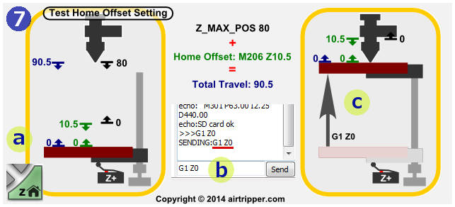
Step 7 – Test Final Home Offset Setting
- Home the 3d printer. The illustration shows how the settings look. The 3d printer LCD would show 90.5 at Z+.
- If you have set the home offset carefully, and there is no risk of a Z axis crash, send g-code G1 Z0.
- The hot end nozzle should now be A4 paper thickness away from the platform. Congratulations, home offset set.
Closing Notes
I hope you found this guide useful, A lot of care was made to avoid mistakes, but if you find any please let me know.
The graphical illustrations should provide a quick guide for return visits to jog the memory when needing to set a new home offset. If you are feeling confident and you find the 3d printer interface software jog controls don’t give you enough fine tuning, use the G1 controlled move command.
[bodyadsrich1l]
Related Articles
Marlin Firmware v1, Basic Configuration Set-up Guide
Marlin Firmware Home Offset Guide Using G-code M206

This is a very useful and simple guide, thank you ! I finished my Mendel90 1 week ago and was always updating configuration.h for Z_AXIS_HOME after measuring so it was very boring. One thing I am missing if my nozzle size is let’s say 0.35mm zero, we should have 0.35mm between nozzle zero position and the bed ?
Also can we also store the E_STEPS_PER_MM value, for example M92 Ennn.nn then M500 ?
Hello,
The gap distance between the nozzle zero position and the bed will be mostly influenced by how well the filament sticks to the bed. With my latest filament, it needs to be pushed right into the bed to prevent warping and lifting around the edges. I think as long as the first layer goes down ok, you are good to go, Getting the exact gap distance to match the nozzle is not vital, subsequent layers will be correct anyway.
Basically, all the settings listed with the M501 g-code command can be set the same way as the home offset.
The Mendel90 is a nice printer, a good design, it should serve you well.
Mark.