Arduino Circuit & Filament Force Sensor
Here’s the electronics and firmware side of things to support the Airtripper Extruder Filament Force Sensor, which includes the Arduino load cell circuit and the Arduino Sketch. Follow the guides in this edition to obtain the parts, to calibrate the Arduino load cell circuit, and then to calibrate the load cell for accurate weight measuring.
Overview
Continuing with the Airtripper Extruder Filament Force Sensor project, this post will introduce you to the basic INA125 instrumental amplifier circuit that requires no soldering. With only a few parts to assemble, for those who often tinker with the 3d printer hardware and know how to update the printer firmware, this project should be a breeze to complete. Experienced electronic hobbyist would probably get by with just the pictures as a quick start guide, while those attempting electronics for the first time will hopefully be able to appreciate the extra help provided in the text. In regards to the Arduino Sketch or Firmware, the software should work with any Arduino load cell project
Since the Arduino load cell circuit is aimed for 3d printer installation, a 12 volt supply will be used to power the circuit. This means that the Arduino UNO will require a 12 volt supply connected to its power jack; either from the 3d printer power supply or AC / DC adaptor. While Arduino UNO USB cable is used in this project, once the calibration is complete, the USB cable could be replace with a wireless module such as Bluetooth to catch data untethered.
The Arduino sketch, which I called the firmware earlier, has two modes of operation. One mode for calibration and one mode for sending data to another application. So that the post doesn’t get too big, only the calibration mode will be covered here. The other mode will be covered in the next instalment of the force sensor project where the Processing Application will be introduced.
Parts Guide
I recommend getting the Texas Instruments INA125 Instrumental Amplifier from a trusted source like Farnell, Digikey, RS Components or similar; you don’t want the risk of landing a counterfeit; if that’s possible with this chip. I know the INA125 chip is expensive but it does an important job with good features, and it’s great that we can get this in a DIP package.
The capacitor is what I had to hand and it’s a 220uf 16v, since the circuit is tested with it, the specification will be added to the bill of materials . As long as the capacitor voltage rating is 16v or over then any similar uf value will do. If you are buying electronics for the first, I should get a spare or two when ordering. Also note the polarity of the Capacitor before inserting it in to the breadboard.
The Cermet Trimmer Pot is used to set the gain on the INA125 Instrumental Amplifier and found 100R was just enough to calibrate the amplifier circuit. While the 100R trimmer pot worked on my circuit, I would suggest getting a 200R trimmer pot also. Using a trimmer pot with of a value much greater than 100R for the gain could effect the stability of the analogue readings. When ordering take note of the arrangement of the legs, ideally you want the legs to be in line rather than staggered for inserting into the breadboard.
The hook up wire is 0.6mm single core wire which is cut to length for a neat breadboard layout. You can use either a jump wire kit or a multi coloured wire pack and both can be found on Ebay. The breadboard can also be found on Ebay and the project uses the 400 pin version.
If you’re on a tight budget like me you can pick-up an Arduino UNO clone off Ebay or you can support the Arduino foundation and get a genuine UNO from a trusted supplier. The project should work with any compatible Arduino board should you own a type already.
This project is based around the 5kg load cell and a guide to how you can get one is found here: load cell guide.
Any files required for the project, such as the Arduino load cell circuit firmware sketch, can be found at the end of this post.
The Arduino Load Cell Breadboard Circuit
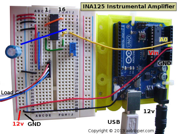
Arduino Load Cell Circuit With Texas Instruments INA125 Instrumental Amplifier – Updated 23/11/13
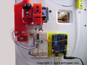
The circuit is simple enough to create on a breadboard as shown in the picture above. The most difficult part will be connecting the load cell if a pin connector crimping kit is not available. Wires on loads cells are very fine and some care will need to be taken to strip the ends ready for connection.
To connect the load cell to the breadboard the wires can be extended with 0.6mm solid single core wire; the same as that used to create the breadboard circuit. Very small terminal block cable connectors could be used, as well as uninsulated bootlace ferrules, to join the load cell wires. Folding back the stripped ends of the load cell wires and twisting them round the wires insulator should provided enough thickness for connectors to grip on.
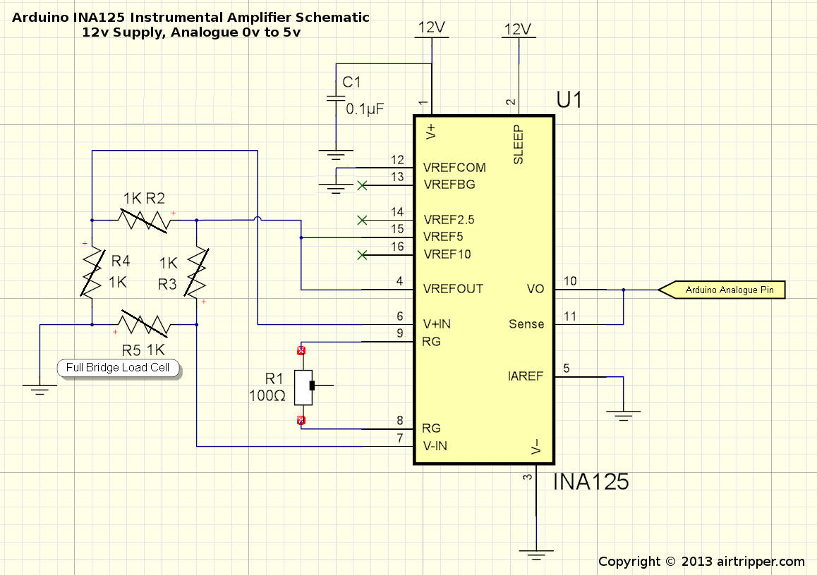
Arduino Load Cell INA125 Instrumental Amplifier Schematic – Updated 23/11/13
The INA125 Instrumental Amplifier is powered from the 12v supply, the load cell supply is powered by the INA125s’ built-in 5v regulator. AREF voltage will also be 5v and the analogue voltage range is from Ground to 5V. Other voltage configurations are possible with the INA125 and you may want to refer to the Data Sheet; link at the end of the post.
The bill of materials below are what I’ve used for my Arduino load cell circuit and I’ve been satisfied with its operation so far.
- Texas Instruments INA125P Instrumental Amplifier
- 100r Wr3296w 10% 3/8 Cermet Trimmer Pot (TSR-3296W-101R)
- Jamicon 220uf 16v Capacitor
- 0.6mm Solid Single Core Wire of different colours
- 400 Point Contact Breadboard
- Arduino UNO
- 5kg Load Cell – Load Cell Guide
- USB Cable for Arduino
- 12v AC/DC Mains Adaptor
- Arduino IDE
Once the circuit is complete, get the Arduino sketch file from the link at the end of the post. Uploaded the sketch to the Arduino UNO and test the Arduino load cell circuit. Using the Arduino IDE Serial Monitor and using a hacked scale to test the load cell, put some weight on the load cell and note what happens to the analogue reads.
If the analogue readings go up when weight is added to the load cell, then all is fine and move on to the next step. If the analogue readings don’t appear to change or going down instead of up, then the load cell may be installed upside down or the blue/green and white load cell wires need to be swapped round.
INA125 Instrumental Amplifier Circuit Calibration
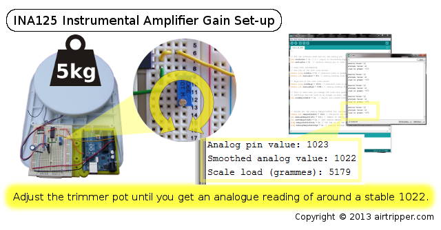
Arduino Load Cell INA125 Instrumental Amplifier Gain Set-up
Rather than mess about with formulas detailed in the INA125 Amplifier data sheet, I went with my own method of calibrating the Arduino load cell circuit. This involve using a trimmer pot to adjust the gain on the INA125 chip to get the voltage range we want for our Arduino analogue pin to read.
Making changes after calibration, like changing wire lengths, altering the circuit and changing the power supply, could upset the gain On the INA125 and cause all other calibrations to be out.
The load cell I’m using is rated for a 5kg load and I want to adjust the gain on the INA125 so that 5v equals 5kg. So basically, I put 5kg on the hacked scale containing the load cell and noted the analogue readings taken from the Arduino load cell circuit using the Arduino IDE Serial Monitor. If the load cell is going to be preloaded with 400 grammes of weight in its intended application, you may want to add this weight to the weight being calibrated. Otherwise you will loose 400 grammes off the target weight range.
The Arduino 10bit A/D converter will give a maximum reading of 1023 and we want to adjust the trimmer pot on the Arduino load cell circuit until 1022/1023 is reached. Ignore the scale load reading at this point as it is yet to be calibrated. Once the gain is set, we can proceed to the next step to calibrate the weight scale of the load cell.
The Filament Force Sensor Firmware
For the Arduino load cell circuit to work it needs firmware in the form of an Arduino IDE sketch. The portion of code below is copied from the sketch which contains variables you need to know to set up the firmware successfully. While the code is well commented, some variables will be covered in more detail in this section and the next section.
// Set the software mode and set the analog pin
int calibrate = 1; // 0 = Output to Processing Application, 1 = Calibration mode
int analogPin = 0; // Arduino analog pin to read
// LOAD CELL CALIBRATION
// Low end of the test load values
static long loadLow = 0; // measured low end load in grammes from good scales
static int analogLow = 80; // analog reading from load cell for low end test load
// High end of the test load values
static long loadHigh = 5103; // measured high end load in grammes from good scales
static int analogHigh = 1008; // analog reading from load cell for high end test load
// This is used when you change the load cell platform to something else that weighs
// different and the load is no longer on zero. Add an offset to set to zero.
int loadAdjustment = 0; // Adjust non loaded load cell to 0
The firmware operates in a mode chosen by the user by setting the calibrate variable to either 0 or 1. Changing modes changes what data is output to the serial interface and what speed the serial interface operates at. Setting the firmware to calibration mode sets the serial baudrate to 9600 and outputs more information to the Arduino IDE serial monitor at 1 second intervals. This mode is ideal for calibrating the Arduino load cell circuit.
Setting calibrate to 0 will set the serial baudrate to 115200 and output just the weight in grammes 100 times a second. Changing the variable plotDelay, not shown in the code snippet, will alter how many times a second data is sent over serial.
The Arduino analogue PIN A0 is used by default and this can be change by assigning a new PIN number to the analogPin variable. Analogue PINs 0 to 5 are available on the Arduino UNO.
Arduino Load Cell Weight Scale Calibration
Calibrating the load cell scale will allow the Arduino code to map grammes to the analogue range that the Arduino load cell circuit can achieve. The calibration, for this application, will achieve a measuring range from zero to 5kg and Zero will be the load cell resting point with no load on the calibration platform. Images are provided as a quick reference to the calibration procedure.
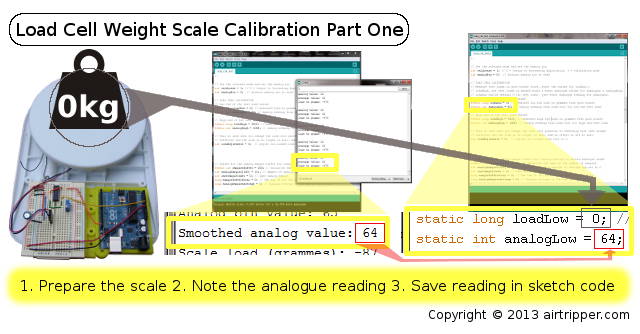
Load Cell Low End Weight Scale Calibration
With the Arduino IDE serial monitor running, note the analogue readings being received from the Arduino load cell circuit. Test the load cell by adding weight to the platform to confirm that the circuit is functioning properly and a good range of readings is possible; you should be getting an analogue range from around 60 to 1022. If the tests look ok then proceed with the calibration, else check the circuit and try the INA125 Instrumental Amplifier gain calibration again.
The first step is to test the low end of the weight scale and you can do this without adding load to the load cell. So the variable loadLow in Arduino sketch code can be assigned 0 as for zero grammes. Then copy the smoothed analogue value to the analogLow variable and move on to the next step.
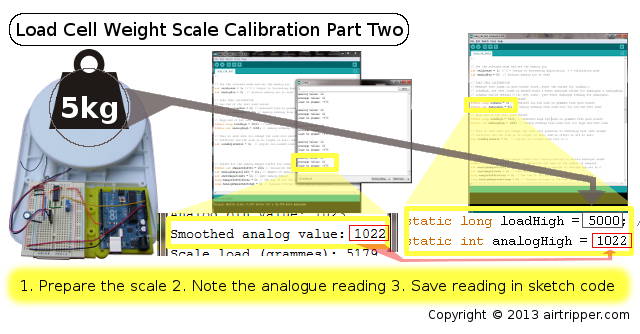
Load Cell High End Weight Scale Calibration
For calibrating the high end of the weight scale some load needs to be put on the load cell scale. The amount of weight to put on the load cell scale should be the amount close to the maximum weight the load cell is rated for. The load being used for calibration should not be so heavy that the analogue readings become stuck at 1023. Adjust the weight so that the analogue readings are a little below 1023.
Measure the weight of a test load as accurately as possible on a good scale, assign the measured weight to the variable loadHigh. Put the test load just weighed on to the load cell platform and copy the analogue reading to the analogHigh variable. Save the Arduino sketch and upload to the Arduino.
The load cell scale should now be calibrated and you can now run weight tests using the Arduino IDE serial monitor for the weight readings.
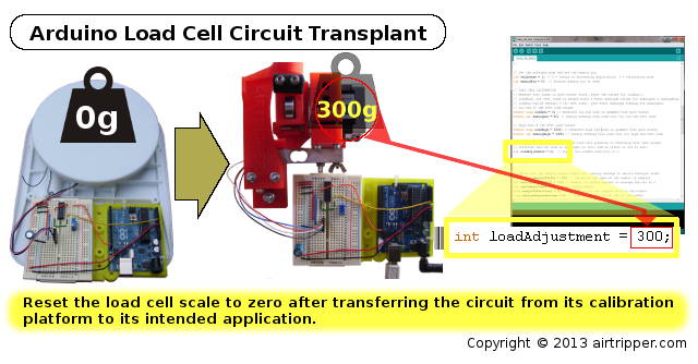
Arduino Load Cell Circuit Transplant
Once the load cell is calibrated it can be transplanted to its intended application. It should be noted that any change in the load cell wire lengths or a change of power supply could effect the gain on the INA125 Instrumental Amplifier and spoil the calibrations.
Setting up the Arduino load cell circuit in another application could change the load cell pre-load weight where zero weight will no longer be set properly. By running the Arduino serial monitor connected to the load cell circuit, you can reset the scale to zero by copying the Scale load (grammes) measure to the variable loadAdjustment.
What Now
The Airtripper Extruder Filament Force Sensor graphing is now done in the Processing Development Environment. This allows me and other users to extend the code and add custom features.
A guide for the Processing Application is being worked on and should be published shortly
The Files
The Arduino load cell Circuit firmware sketch file : https://github.com/Airtripper/load-cell-test
Related Articles
3D Printer Extruder Filament Drive Gear Review & Benchmark
Electronic Kitchen Scales Teardown Versus Load Cells
Airtripper Extruder Filament Force Sensor – Introduction
[bodyadsrich1l]
I hope you found the Arduino Load Cell Circuit & Sketch for Calibration interesting and helpful.

Hey Mark, AWESOME BLOG 🙂 Do you have any info how to subscribe to your blog via mail? Is that possible? Jeez, everything changed for me since Google Reader is dead 😀
//Thanks Flo
Hi Mark, another great article.
Do you have a circuit diagram by any chance?
Regards
William
Hi William,
With the simple breadboard layout I didn’t bother with the circuit diagram for this post. I’m going to do another topic on the INA125 with other circuit examples but I can add a circuit diagram to this post, it shouldn’t take me long to get one sorted.
Mark
I would like to ask , my monitor shows values from 0 to 100 grams , is it possible to change the algorithm so to have the circuit read values , for example 10 or 50 gramms? Thank you
Hi,
The purpose of the firmware is just to read the analogue values and convert them to grams with a bit of smoothing. Any requirements beyond that you will need to add your own code.
You could add an “else if” like in the following code snippet to point to your own subroutines.
if (calibrate) {// print test results
Serial.print(“Analog pin value: “);Serial.println(analogValue);
Serial.print(“Smoothed analog value: “);Serial.println(analogSamplesAverage);
Serial.print(“Scale load (grammes): “);Serial.println(loadGrams);
Serial.println(” “);
} else if (calibrate == 2) { // remember to change the calibrate variable to 2
// Your code here
} else { // Output to Processing as such
Serial.println(loadGrams);
}
To execute your “else if” block just change the calibrate variable to 2.
You will need to pass variables such as loadGrams, analogValue and analogSamplesAverage to your own subroutines if you plan to use the values they contain.
“Making changes after calibration, like changing wire lengths, altering the circuit and changing the power supply, could upset the gain On the INA125 and cause all other calibrations to be out.”
Any solution to that problem? Mostly the power supply problem. Every time you disconnect the dc power you need to recalibrate. Thank you
Hi,
Using the circuit example in this article has been very stable over months of use. This is due to using the INA125 on chip regulated supply to excite the load cell and using the same wires, between the load cell and circuit, for calibration and final application.
Disconnecting and reconnecting the power supply has not caused calibration issues in my experience, also I’ve been able to swap to a different 12v power supply without issues. Changing from 12v to 10v, or visa versa, could cause a change in calibration.
The Arduino, which provide 10 bits of resolution (i.e. 1024 different values), has an analogue resolution too low for a completely stable load cell scale. The smoothing algorithm in the firmware helps to provided more stable load cell reading.
Hi Mark,
I’m getting waht look like good data from the Adruino; what did you use to display it as a graph?
I’m still working on the graphing application and about to convert the graphing code into a library.
However, if you are ready to add graphing to your project, I’ll send you the code via email that you can load into the Processing application.
The processing application must be the 32 bit version to work with the serial interface.
It will likely be tomorrow evening before I can send it you.
Mark
Hi Mark,
that would be great, but don’t feel you need to rush for me; I’ve plenty of other things to amuse myself with at the moment.
I’m messing with a E3d all metal hotend and trying to get the optium temp/speed etc. Seems better than my previous hotend which worked well for a while, but then the PTFE seemed to start breaking up.
Regards
William
I may be missing something, but shouldn’t we call a analogReference(External); in the code to have the arduino reference the ina125’s voltage? Otherwise aren’t we tying the arduino’s 5v ref voltage and the ina125’s ref voltages together (which may have slight discrepancies and thus current flow between the two)? See http://arduino.cc/en/Reference/AnalogReference
I am also unclear as to why pin 12 isn’t tied to ground on your schematic or breadboard?
……OK, after reflection I believe we should apply the two changes listed above (code and ground) to take full advantage of the ina125’s regulator.
Thanks Jess, I appreciate the feedback.
It looks like I have indeed made a mistake with the Arduino voltage reference configuration. I originally thought that the Aduino automatically switched to the external voltage reference when a voltage was applied to the AREF PIN. The Arduino was probably saved due to the internal voltage being the same as the external when shorted.
For this application, the Arduino internal voltage reference should be used and the Arduino AREF PIN should be disconnected. This decision is made due to the external voltage reference, applied from the INA125, measuring more than 5v (5.77v), possibly exceeding the Arduino AREF PIN voltage limit.
No changes to the code is necessary and the Schematic and circuit in this article will be updated with the AREF connection removed.
The INA125 PIN 12(VREFCOM) was left floating since there was enough voltage headroom to calibrate the load cell. I’ll have to investigate VREFCOM when I get a bit of time,
but for this article, the circuit will work well enough without it. This article serves as a starting point for working with the IAN125 and it is likely that the more experienced will want to access more features of the chip, and that’s fine.After some investigation I’ve decided to amend the breadboard circuit and schematic to include connecting the VREFCOM to ground. The resistance range for gain was much smaller than what would have been and kept within the limits of the 100R trimmer pot.
Mark
Hi,
you use 5kg load cell right…
can i apply 180kg load cell ?
Hello,
You could use any load cell I guess, the issue you will have is the final measuring resolution after calibration. 180KG load cell might have a resolution of around 200grams through an 10bit analogue microcontroller input such as on the Arduino UNO. The Teensy 3.1 microcontroller will provide better resolution; High Resolution Analog Inputs (13 bits usable, 16 bit hardware).
If you need better resolution than what can be provided by the microcontrollers, try the 24bit HX711 Dual-Channel Weighing Sensor Module. The reads will be much slower, but fast enough if you are just weighing stuff.
Mark
Hi,
sir, I really don’t know much about,
I use the combination of 3 wires load cell (Red, White and Black wire) which give out 4 pin labelled as S+ S- E+ E-
I want these 4 pin into INA125P , as Vout from INA125P connect to arduino Uno to convert the value to kilograms as I want to calculate the people weight..
Kindly need your help sir…
Ammar
Hello,
I’ve not tried using the 3 wire load cells yet but I believe you have the half bridge type.
To use the circuit in this article, you will need to convert your load cell to a full bridge. The links below point to discussions about converting a 3 wire half bridge load cell to a 4 wire full bridge load cell.
The software for the Arduino outputs grammes but the code can easily edited to output Kg instead, I can help with that when you are ready.
http://www.electro-tech-online.com/threads/3-wire-load-cell-question.32536/
https://forum.allaboutcircuits.com/showthread.php?t=84383
Mark