Welcome to my new blog series called 3D Printer Surgery where you will learn about the tweaks and upgrades I am making to my SUMPOD 3D Printer. Hopefully, the series will be of interest to any 3D Printer owner who wishes to make their printer more user friendly, more productive and importantly, more reliable.
 In this edition I am going to share the details of the new Z axis handle I’ve fitted on to the SUMPOD 3D Printer. I’m also going to demonstrate how easy it is to print your own Z axis handle. Although this edition is more catered for the SUMPOD owners, there are useful tips about printing tall items that any 3D Printer owner would appreciate.
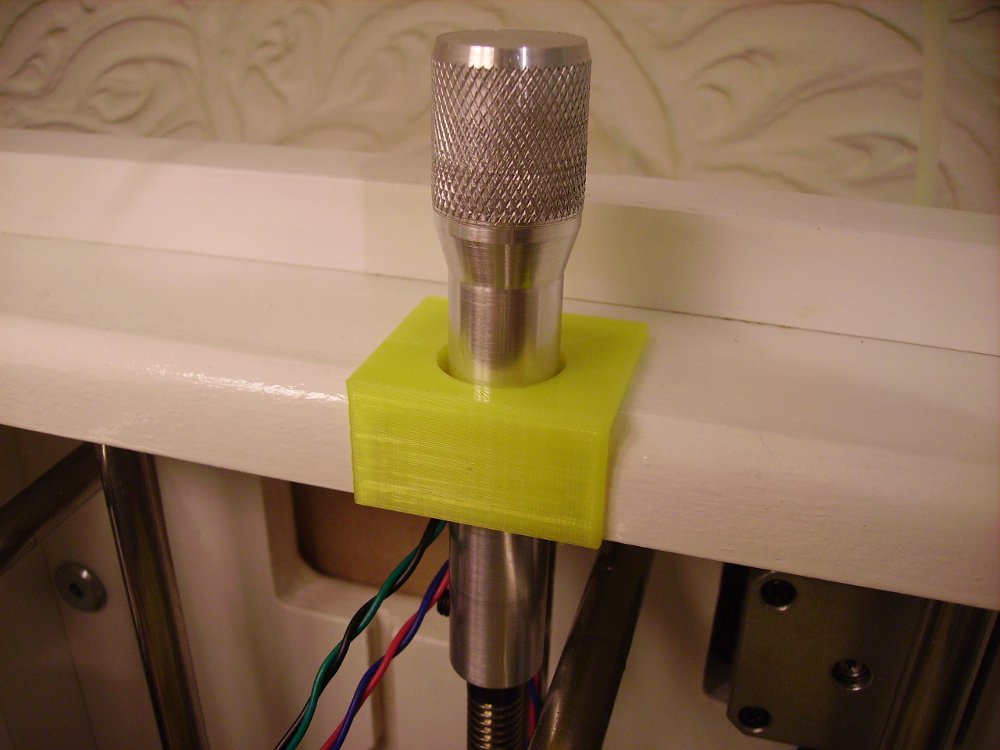
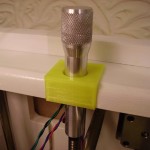
I must admit, A Z axis handle was not a feature I planned to install, mainly because I did not fancy taking a hacksaw to my nicely painted printer, even if I was sticking my hand in the printer to manually turn the leadscrew. With many thanks to Mike at 3d-printer-kit.com, I now have a nice, shiny new hand made Z axis handle. Mike appreciated the work I’ve put in to Skeinforge to help him and other SUMPOD owners get their first 3D prints off the platform, and very kindly offered to make me a z axis handle.
 The Z axis handle is certainly a nice feature to have, and it does help to get that last adjustment in, to get that nozzle just right above the platform during the skirt printing phase.
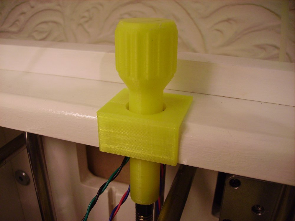
I would recommend any SUMPOD owner to fit a Z axis handle on their machine, and in order to support that recommendation further, I decided to see how easy it was to design and print one.
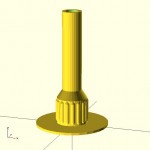
Designing the Z axis handle was done with OpenScad, which is a popular open source application used by many 3D Printer owners. This was my second attempt on the design because the first attempt failed during printing because of excessive warping, causing the 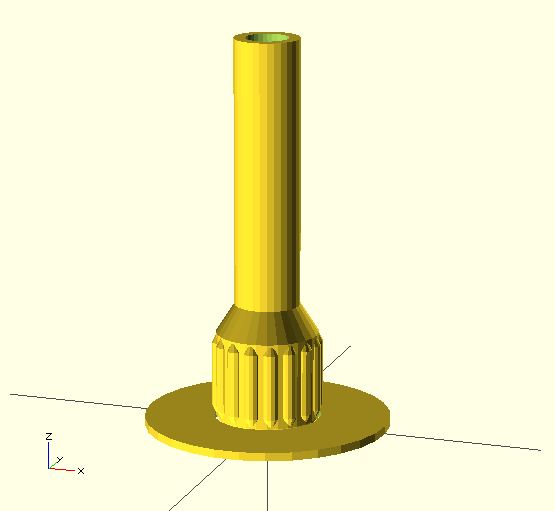 print to topple over. Despite having a heated platform, the warping was not avoided. I think the warping was caused by a combination of slow printing speed and small footprint on a tall model.
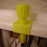
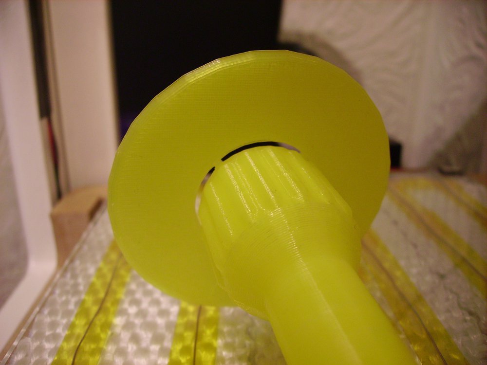
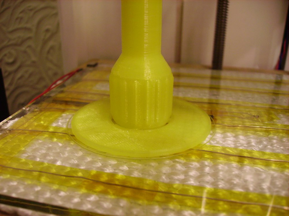
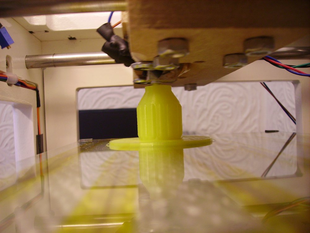
I set about increasing the size of the footprint, a process quite easy in OpenScad, just by altering a few numbers in the code. In fact, a larger knob worked best for improved grip for operating the handle, and it looked better than the original design. Just to be on the safe side, I decided to add a plain around the handle to ensure stability during printing. If there is going to be any warping on the handle, the plain will keep the Z handle anchored down. Now I’m happy with the model, to increase printing speed, I decided to give the Marlin firmware a go. It took a couple of hours to set 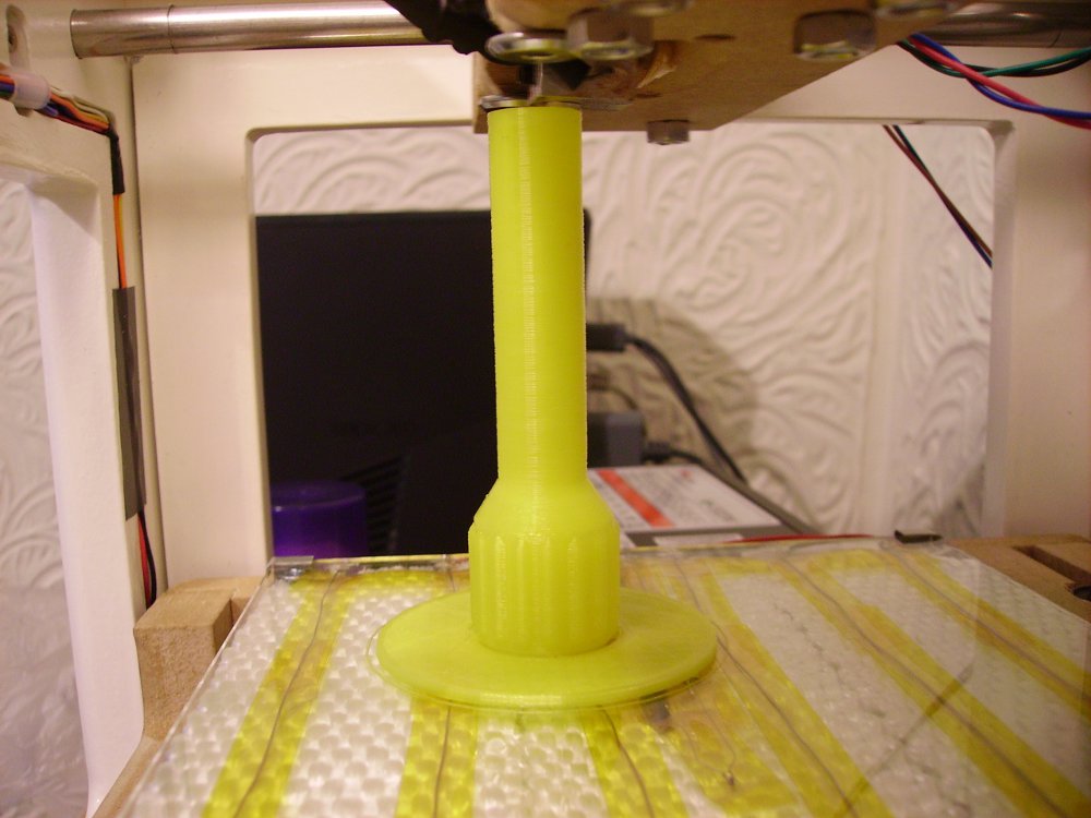 up, and made a successful test print at a much quicker pace than I could get with the Sprinter firmware, I was ready to go. Made a couple of changes in Skeinforge, because I’m using Marlin, I reduced layer time to 30 seconds under Cool and removed Z axis move from end.gcode file to avoid crushing the handle at the end of the print. I thought it was best to limit the print speed on the thin part so each layer has a chance to solidify before taking on more plastic.
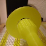
The 3D print took a little under 4 hours and was a success, no warping in the handle, and the handle and plain was stuck down real good on the glass. As the heated glass platform cooled, you can hear the base of the plastic starting to dislodge itself. Soon, I was able to remove the handle from the glass bed. The plain snapped off the handle easily, leaving small notches behind. These were easily remove with a file. Putting a bit of electrician’s tape around the top of the Z leadscrew was enough to secure the handle in to position. As you can see in the picture above, the printed plastic Z axis handle and bezel look awesome!
Hope you enjoyed reading the first edition of 3D Printer Surgery. You will find more pictures and a video clip after the jump, the OpenScad and STL files for the Z Axis Handle and Bezel are available to download below.
The next edition of 3D Printer Surgery will be about lighting up the build area with dimmable L.E.D. lights.
Download OpenScad Z Handle and Bezel files
-
- 3D Printer Metal Z Handle Fitted

-
- 3D Printer Plastic Z Handle Fitted

-
- 3D Printer Z Handle Bottom of Base Close Up
-
- 3D Printer Z Handle Top Of Base Close Up
-
- 3D Printer Z Handle with Base Stuck Down Close Up
-
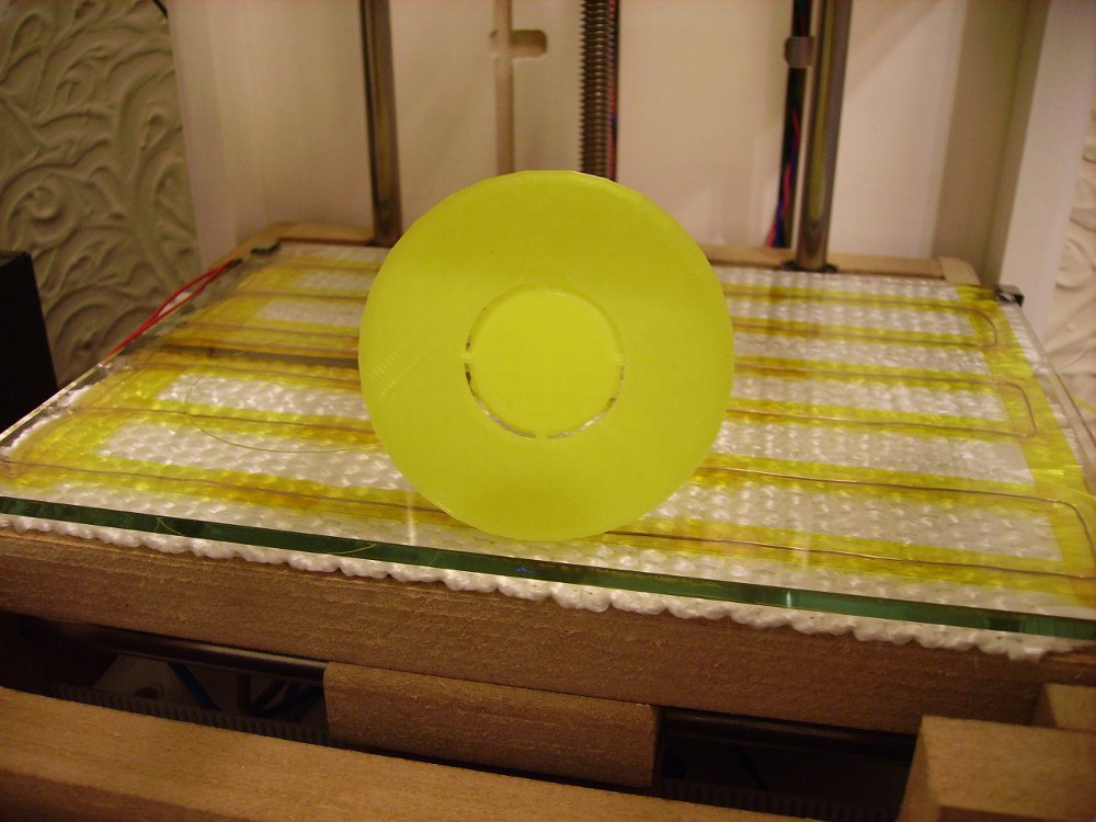
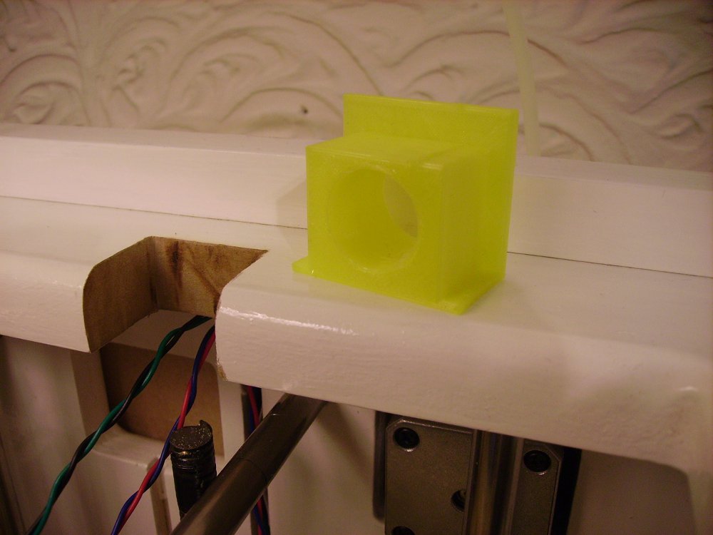
- 3D Printer Z Handle Cut Out With Plastic Printed Bezel
-
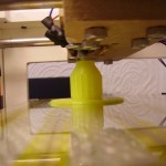
- 3D Printer Z Handle Close To End Of Print

-
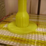
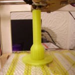
- 3D Printer Z Handle During Printing
-
- Z Handle in OpenScad


Nice work! It proves the whole concept of 3D printing as anyone with the access and printer can make one. No postage, or delays anywhere in the world!
You may want to consider putting the .stl file on Thingiverse since that allows easy access to your design. I put my printing table clips (9 downloads), SD card reader bracket (just listed, 2 downloads) and a plain Z axis handle (like yours better :), 14 downloads) so others can share you efforts.
Mike (Brixham Engineer)
Excellent work.
Nice and it looks great. I imagine this part will be on many a SumPoder’s list of things to printed when they finish their machine. Sharing stuff on Thingiverse is a good idea, but could you also include scad file.
Matt aka Fixer
Opps, I just spotted the download link for the scad files at the end of your post. I’m learning OpenSCAD and working with files I will actually print and physically handle (bad pun intended) is helpful.
Hi Matt
I’m having a hard time printing your nice handle. Do you remember the temperature and speed settings you used? For the 4th attempt, I went down to 15mm/s for perimeters and 20 mm/s for infill at 195°C with a min. layertime of 15s. This attempt is currently running and I don’t know yet, if this will work for the shaft.
Cheers,
Andy
At a guess, your layers are not cooling fast enough to accept the next layer which causes just printed layers to be moved out of shape before they have a chance to set.
Also, because the layers are small, the hot end slows cooling.
Some people have a fan on their 3d printer to blow across the layers with good results at higher printing speeds.
However, Skeinforge has a Cool tab that you can activate. Just set Minimum Layer Time to 60 seconds, this will give each layer a minute to set before taking the next layer. Printing will be a bit slow, but the results are good.
Hope this helps,
Mark
Many thanks for your hints. It finally worked, yessss 🙂
Fortunately, I didn’t have to go as low as 60 seconds per layer but could stay with the 15/20 mm/s.
Cheers,
Andy