In the second post of the 3D Printer Surgery Series I’ll be looking at upgrading the SUMPOD 3D Printer extruder, or filament pusher. I’ll be posting the upgrade process from start to finish so that anybody who is new to 3D printing can get an idea on the development process. In part one I’ll be focusing on getting the non printable hardware side of things together for the filament pusher, and then create the hardware in OpenSCAD – The Programmers Solid 3D CAD Modeller. By the End of the post, I will have a virtual stepper motor assembly to model the 3D printable part around.
 |
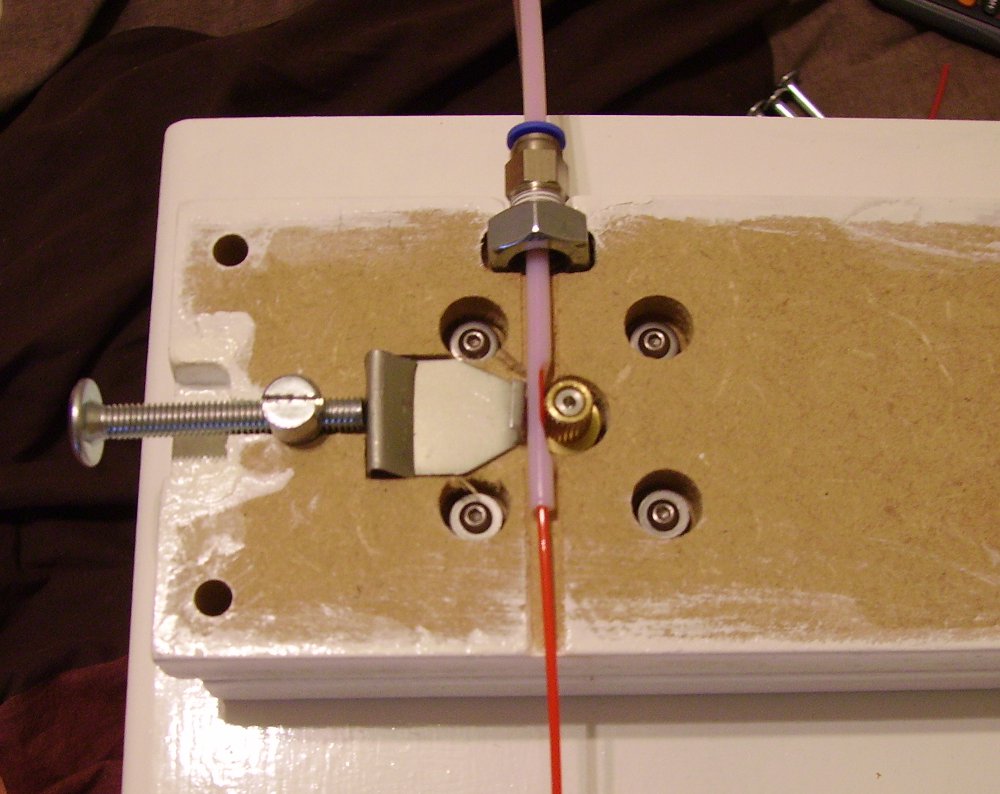 |
I had planned to do a post about adding a dimmable lighting feature to the SUMPOD 3D Printer but had difficulties in extruding some of the 1.75mm filament I was using to print the lighting fixtures. I opted to buy the cheaper filament that was available around Europe which in most cases, can be less than half the price of the filament that can be sourced in the UK or America. As far as I can tell, the SUMPOD community appears to be getting better 3D printing performance out of using the more expensive filament. However, I’m not ready to give up on the cheaper filament just yet. I’m going to do some upgrading, starting with the extruder, and hopefully be able to continue using the cheaper filament with more reliability. I should point out that the SUMPOD extruder plunger modding I installed was a replacement for the plunger I lost that was delivered in the SUMPOD kit. The original plunger may have worked much better than my modded version.
 Instead of just downloading a design from thingiverse.com, I decided to have a go at designing my own 3D printer extruder. For my first extruder upgrade, I’m just going to keep it as simple as possible and go for the Stepstruder style design. This design will offer improvements such as the use of a bearing instead of a plunger to reduce filament friction. Another welcome improvement will be for easier filament loading. So, without further ado, lets get started on the new 3D printer extruder.
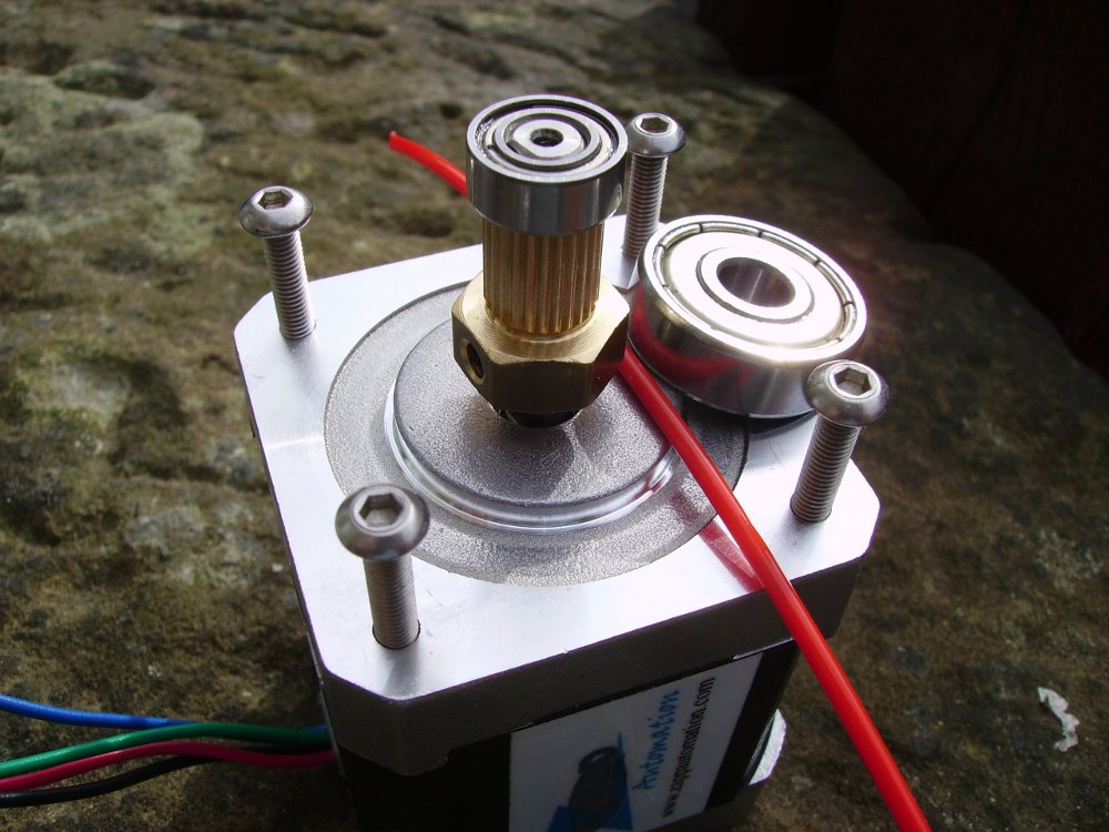
 To make it easier to design the 3D printable components of the extruder, I’m going to also include the non printable components of the extruder in to the design. This includes the stepper motor, bearings, screws and insert which are created easily using primitive solids. Each of these non printable components will be created separately, and then added together to produce a partly completed 3D printer extruder. In part 2 of the Extruder Upgrade I will be going over the process of designing the printable component to complete the 3D printer extruder. Continue reading to learn more about the design process of the individual components and how the components are put together.
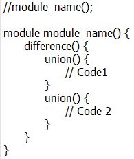 In OpenSCAD I usually start with a template to save typing and it takes the form as what you see in the image on the left. The first line starts with two forward slashes which tells the compiler not to execute this line. This is known as comment out, and usually used when adding descriptive text about lines or blocks of code. The forward slashes are commonly used to activate or deactivate modules in a OpenSCAD script. This allows you to compile only the parts of the 3D model you want to view and export. After the first line there is a block of code declared as a module. This module will only be compiled when the first line has the comment out forward slashes removed and the module name matches.
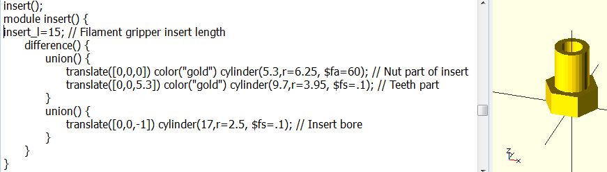 The above image represents the insert that will fit on to the stepper motor shaft to grip the filament. Only 3 lines of script is needed to be added to the template script shown earlier to create the insert. This 3D part is contained in a module called insert and it is called by using the first line in the above script. Three primitive solids are used to create the insert, the first two combined in the first union block and the third, while not required to be in a union block, is used to subtract from the first union block because both union blocks are contained in the difference block.
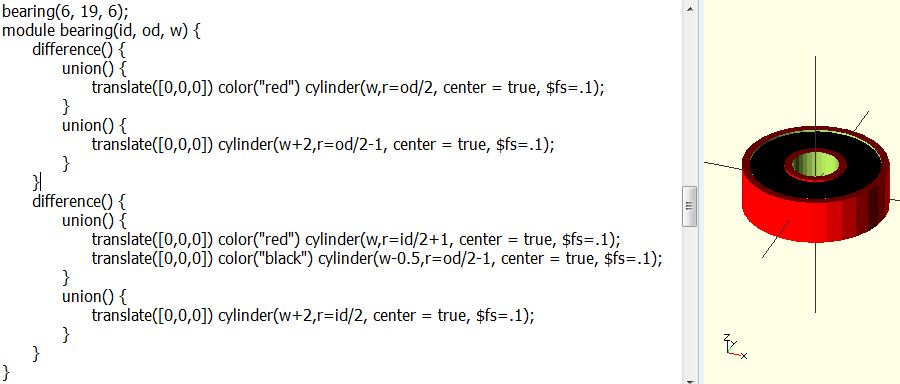 The above script is a bit more complicated because parametric equations are used to construct the 3D model – in this case a ball bearing. This allows me to reuse the same script to create different size ball bearing models just by passing three values when calling the bearing module. The three values required are the ball bearing measurements which include inner diameter (id), outer diameter (od) and width (w).
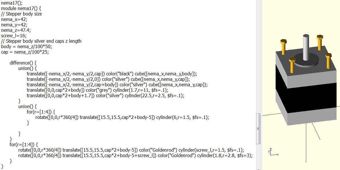 The Nema 17 stepper motor OpenSCAD model is shown above with the script which contains some parametric equations. The purpose of the equations are just to align primitives in relation to other primitives along the z axis. The screws in the 3D model are there as a guide while the printable part of the extruder is being designed. The OpenSCAD script will be altered once the length of the screw has been determined.
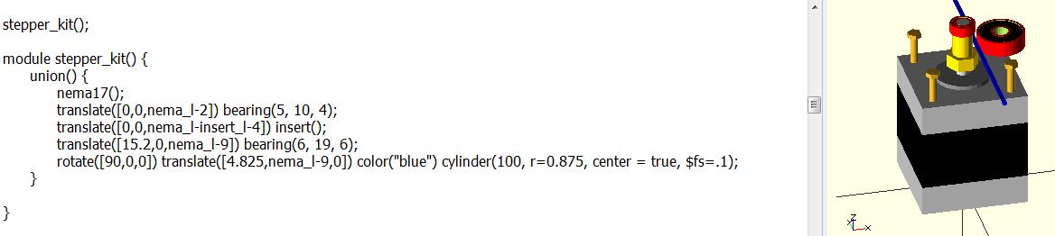 The final OpenSCAD script, shown above, assembles all the different components to make a partially completed 3D printer extruder. The 3D printable components can now be designed around this assembly and having an instant view of the complete assembly at the same time. This script is a module that calls other modules for each component required for the 3D printer extruder assembly, it also positions and rotates the different components so they fit together correctly. I’ve made the OpenSCAD file available to download so that you can mess with the script yourself.
[bodyadsrich1l]
Download Zipped OpenSCAD file: stepper_kit OpenSCAD file.

Hi Mark,
I’ve just added a hot bed to my sumpod, based on your design, and the results are very much better than the old ‘cold’ blue tape. The main difference is that i’ve ended up using a piece of mirror as I had that to hand. Interesting illusion, a bit like a mirage. I used a single length of 20 swg nichrome wire, which is OK but is a bit like wresting with an anaconda to get it stuck onto the glass.
Hope to start printing out the parts for your extruder soon.
Thanks for publishing all your notes,
William
On some PLA filament stock, you might have to tweak settings to reduce warping completely. The heated glass bed has been a great addition, I have been meaning to do a better write-up on it but the extruder upgrade has been a priority.
The new extruder has been great and now looking forward to a new control panel with click encoder and SD card slot. This will be built around the latest Marlin firmware to ensure an easy firmware upgrade path with minimum set up. The notes will be posted in multiple parts hopefully starting next week.
Mark