Continuing the Airtripper Extruder Filament Force Sensor series this topic is about getting the plastic parts configured to fit the chosen load cell. Included is a guide to configure the OpenSCAD model file with image references for most of the variables for easy set-up. Be sure to read the section “Choosing A Load Cell” for a guide to getting a load cell to fit the filament force sensor bracket.
Documentation for the electronics and software is currently being edited and will be published shortly.
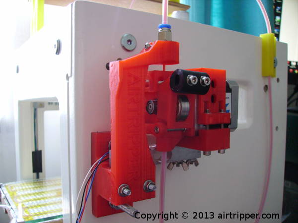
The Load Cell Bracket
The current force sensor bracket is designed to be configurable to suit a common load cell size configuration with small variances in screw hole positions and sizes. Only two revisions of the bracket have been printed, to test different load cells, and no failures have developed with the plastic parts after many hours of use. A few tweaks have since been made to bulk up the bracket design to improve stiffness and more 3d printable for other makers.
The force sensor bracket design and the OpenSCAD model file was made to be as distribution friendly as possible to allow other makers to get involved in the project as easily as possible. For now, the current bracket configuration only supports 1.75mm filament but 3mm filament support is on the way with a new extruder design. While the force sensor bracket uses the Airtripper bowden extruder, other direct drive extruders that support 1.75mm or 3mm filament could be made to fit.
It was decided, for a bowden extruder set-up, that a 5kg load cell was sufficient. It was found that an extrusion force of more than 2.8kg (approximately) over a long periods of time would strain the push fit fitting holding the PTFE tube. One push fit fitting had failed, but after many hours of use. However, as well as the high extrusion force, the pushing and pulling of the retraction operation may be a high contributing factor of the fitting failure.
A normal working filament extrusion force has not been defined that I know of but some of the better filament I’m using requires less than 2kg of force at 24mm/s, 0.25mm layer height and 0.4mm nozzle. While I’ve been using the filament force sensor I’ve noticed that the filament is requiring more force to extrude as it ages. Probably a good time to think about my filament storage strategy.
Choosing a Load Cell
The load cell required for the Airtripper Extruder Filament Force Sensor should have a 5kg load rating and be at least 75mm in length. How you’ll get the load cell will depend on the resources you have to get the load cell calibrated. A guide about acquiring load cells can be found here: Electronic Kitchen Scales Teardown Versus Load Cells.
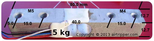
5kg Load Cell Bought from Ebay
The above load cell is similar to what you need and the dimensions you see are used in the OpenSCAD model file to configure the filament force sensor bracket. As long as the load cell is at least 75mm long and about 13mm wide then the load cell should fit the bracket after some configuration.
Load Cell Bracket – Configure The Parts
Since load cells from different sources have features with measurements that vary, it is necessary to configure the OpenSCAD file to produce the correct STL files. This should be easy to do even if you are new to the OpenSCAD application, there should be enough information in this guide to successfully reach the 3d printing stage of the project.
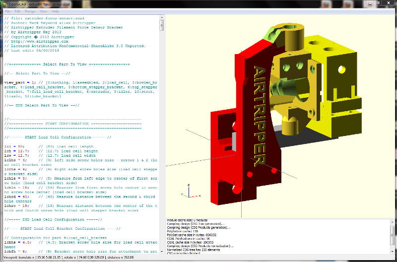
OpenSCAD Application Window View
Getting Familiar With Model File
At this stage you have the load cell you are going to use and measured up similar to the example shown above. You’ve got OpenSCAD installed on the computer, running and got familiar with the software interface. Press F5 to refresh the model window after editing code, and press F6 to compile the model before choosing to export to STL file.
Before configuring the OpenSCAD file with the load cell measurements, we need to get familiar with some code in the file in order to get the model view we want in the render window. Loading the project file into OpenSCAD will automatically render any object that is configured in code to show in the render window.
The OpenSCAD model file supplied for this project, if I remember to set it correctly, should show by default the assembled model (1:assembled) of the Airtripper Extruder Filament Force Sensor. The models in the file are partly parametric and the assembled model should adjust itself to reflect the entered dimensions of the load cell. The load cell should correctly fit the brackets as long as the assembly screw holes line up. After entering new load cell dimensions, it will be a case of rotating the assembled model in 3d view to check screw holes are aligned.
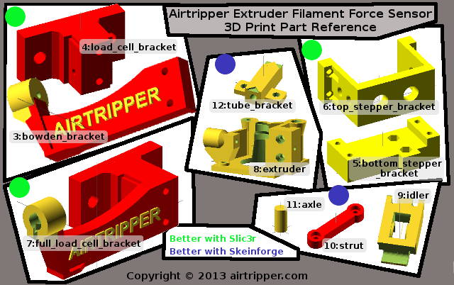
Selecting A Model To View in OpenSCAD
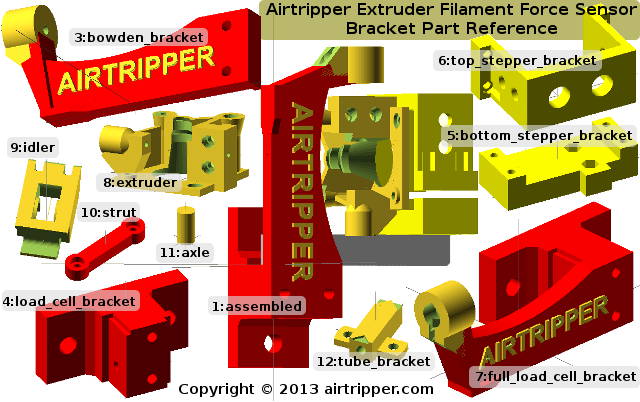
The bracket part reference guide above shows the models available for selection to view and edit in the OpenSCAD filament force sensor project file. A number is assigned to each model and is used in the OpenSCAD project file to select which model we want to view in the render window. The following code from the project file is used for selecting a model to view in the render window; it’s the first bit of code in the file.
//– Select Part To View –//
view_part = 1; // [0:nothing, 1:assembled, 2:load_cell, 3:bowden_bracket…
//– END Select Part To View –//
In the code file, anything after the two forward slashes ” // ” are just comments to help describe some code.
The above line of code shows that 1 is assigned to view_part variable and this will cause the project file to display the assembled filament force sensor kit. Changing the assigned 1 to a different number that is associated to a different model in the part reference guide will cause the OpenSCAD render window to update after a compile command (F5) is issued.
Tip: When exporting the rendered model to STL, it is recommended to use the model name as the file name.
Load Cell Configuration
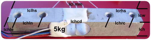
5kg Load Cell Size Variables
//—— START Load Cell Configuration——-//
lcl = 80; // (80) Load cell length
lch = 12.7; // (12.7) Load cell height
lcw = 12.7; // (12.7) Load cell width
lclhs = 4; // (4) Left side screw holes size – screws 1 & 2 (load cell bracket side)
lcrhs = 4; // (4) Right side screw holes size (load cell stepper bracket side)
lchle = 5; // (5) Measure from left edge to center of first screw hole (load cell bracket side)
lchln = 15; // (15) Measure from first screw hole center to second screw hole center (load cell bracket side)
lchcd = 40; // (40) Measure distance between the second & third hole centers
lchrc = 15; // (15) Measure distance between the center of the third and fourth screw hole (load cell stepper bracket side)
//—– END Load Cell Configuration —–//
The above code is found in the model file and allows you to enter new load cell dimensions so that the extruder filament force sensor can be configured to fit the chosen load cell. The load cell image above the code shows the variables at positions where measurement values are taken from; this serves as a simple and quick reference to identify each variable association.
When making changes to the load cell dimensions, render the 3d view (F5) to review the changes. With the assembled model in view (1:assembled), rotate the model to check that the changed feature is still aligned correctly.
Configure Bracket & Screw Holes
After the new load cell dimensions have been entered in to the project file we now need to sort out what screw sizes to use to attach and assemble the brackets. Refer to the image below to quickly identify variables used.
Please Note – Screw Sizes
Default screw hole sizes are oversized to allow for shrinkage when 3d printed, and the measurements have been fine with my particular 3d printer & filament set-up. When reviewing the screw hole sizes you will need to determine how much shrinkage allowance you want to add in order for the screws to fit.
Hex nut capture sockets for screw heads will be most sensitive to filament & 3d printer configuration, and so it is advised to do a test print using a small part with the screw sizes you want. Hex head socket being the wrong size could render your newly printed part unusable; wrong size hex nut sockets could make it difficult to assemble the parts.
To avoid complications, the filament force sensor bracket has been designed not to rely on load cells having particular screw hole designs. This means in most cases the default settings for lcbhs, sbsd & sbsdh will not need to be changed.
Variable lcbhs will be an M4 screw with 2 fitting options:
- Screw into the load cell from underneath the bracket – load cell screw hole is M4 threaded.
- Push all the way through the bracket and load cell, and fasten with a nut – load cell screw hole is not threaded or the screw hole is M5 threaded.
Variables sbsd & sbsdh should always be at the default setting for M3 screws which allow for a wider stepper motor position adjustment. M4 Screw size can be used if more convenient but the load cell screw holes must be big enough to allow the screws to drop through for nut fastening.
The load cell bracket attachment screw holes lcbfh are adjustable and are used for attaching the bracket to the printer or other surface. The default size is 8mm, for M6 screws, to allow for 3d print hole shrinkage and screw hole misalignments.
Variable lcbss can be updated to adjust the distance between the lcbfh screw hole centres. If you are replacing the Airtripper extruder with the bracket, setting lcbss to 60mm will allow the bracket to fit the holes used for the extruder; saving extra drilling.
The bracket is designed to fit NEMA 17 stepper motors and the variable smw allows some adjustment to the stepper motor clamp width. It is important that the stepper motor is fitted loose enough inside the clamp so adjustments for alignment can be made before the clamp is finally tightened. Adding 1.5mm to 2mm to the stepper motor width when updating the smw variable will reduce the chances of the stepper motor snagging inside the clamp during set-up.
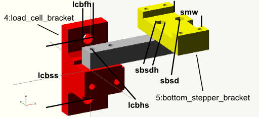
Load Cell Bracket Variables
Load Cell Bracket Variables
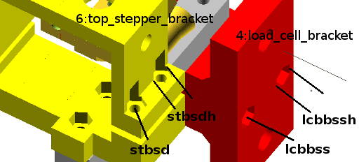
Variables stbsd, stbsdh, lcbbss & lcbbssh are available to fine tune for your 3d printer & filament set-up.
Find the configuration code, shown below, in the model file to make the necessary adjustments as described above.
//—- START Load Cell Bracket Configuration —-//
// Configuration for part 4:load_cell_bracket
lcbhs = 4.5; // (4.5) Bracket screw hole size for load cell attachment
lcbfh = 8; // (8) Bracket screw hole size for attachment to printer
lcbss = 46; // (46) Bracket fixing screw holes distance apart, hole centre to hole centre
lcbbss = 4.5; // (4.5) Bowden bracket attachment screw size
lcbbssh = 8.4; // (8.4) Bowden bracket attachment screw Hex head size
//– END Load Cell Bracket Configuration–//
//—- START Stepper Motor Bottom Bracket Configuration—-//
// Configuration for part 5:bottom_stepper_bracket
smw = 44; // NEMA 17 stepper motor case width
// Stepper motor bottom bracket load cell attachment screw size
sbsd = 3.5; // (M3 = 3.5)(M4 = 4.5) Screw size
sbsdh = 7.5; // (M3 = 7.5)(M4 = 8.8) Screw Hex head size
//– END Stepper Motor Bottom Bracket Configuration –//
//—- START Stepper Motor Top Bracket Configuration—-//
// Configuration for part 6:top_stepper_bracket
// Stepper motor Top bracket load cell attachment acrew size
stbsd = 3.5; // (M3 = 3.5)(M4 = 4.5) Screw size
stbsdh = 7.5; // (M3 = 7.5)(M4 = 8.8) Screw Hex head size
//– END Stepper Motor Top Bracket Configuration –//
3D Printing & Building The Parts
Skeinforge has been my number one slicing application and it has worked great in producing g-code for the Airtripper Direct Drive Bowden extruder parts. Between Slic3r and Skeinforge, Skeinforge is still the better slicer for the extruder. Other slicers may work very well, but for this project, I’m just going to report what I used successfully with good results.
While Skeinforge worked great for the Airtripper extruder parts, it was not the best choice for the load cell brackets. I found that Skeinforge added too many solid layers in the larger parts which caused poor 3d printed results where there was many consecutive solid layers. Not sure why Skeinforge adds the extra solid layers, but decided that slic3r worked better for the filament force sensor brackets; only putting in solid layers where needed.
Export The Parts
//– Select Part To View –//
view_part = 1; // [0:nothing, 1:assembled, 2:load_cell, 3:bowden_bracket…
//– END Select Part To View –//
Once you are sorted with the OpenSCAD file configuration, locate the above code in the scad file and change the number assigned to view_part to the next model you want to export to STL file for slicing. Use the part reference image above to quickly identify the parts to be 3d printed. In the OpenSCAD application menu “Design” select Compile and Render, and then select Export as STL under the same menu. Use the model name as the file name as you export each model.
The 4:load_cell_bracket and the 3:bowden_backet can be printed in one piece if desired. The one piece bracket, 7:full_load_cell_bracket, was too big for my 3d printer platform.
3D Printing The Parts
Below are some bullet points about the set-up I used for the brackets and the extruder. The settings are more of a starting point than recommendations set in stone.
- All the parts set to 0.3 infill density.
- Minimum two perimeters.
- Solid layers, three top and three bottom.
- Set a cooling threshold for parts 3:bowden_backet & 7:full_load_cell_bracket. The BSP push fitting socket can spoil without adequate cooling.
- All the parts printed with 0.25 layer height.
- Solid infill every 6 layers for parts 3:bowden_backet & 7:full_load_cell_bracket. This was to add stiffness to the bowden tube bracket.

Electrical Tape Added For Padding & Protecting
Building The Parts & BOM
The force sensor bracket assembly will be detailed here while the Airtripper bowden extruder assembly is covered here: Airtripper’s Bowden Extruder V3 – Updated Design. Also note that the bill of materials is based on the default set-up of the OpenSCAD file. However, note the lengths of the screws required when ordering the screws you have configured for your set-up.
Tip
For the purpose of prototyping, I usually keep a stock of screw sizes of the longer lengths and cut them down with a Dremel to the required length. This saves on storage space and keeps the stock of screws to a minimum, and also cuts the cost of getting screws of all sizes.
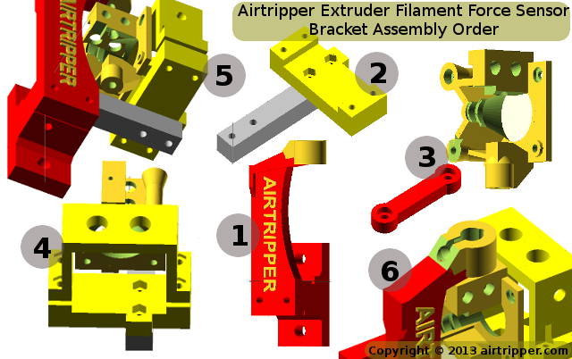
Six steps have been defined to assemble the filament force sensor bracket and by using the image above against the numbered bullet list below the assembly should go smoothly.
- First, if the two part version was printed, attach the bowden tube bracket to the load cell bracket with M4 screws pushed through the back. Tighten the nuts and attach the load cell bracket to the printer or other chosen surface.
- 2 x M4 x 40mm Hex Head Bolts
- 2 x M4 Full Hex Nuts
- 2 x M4 Washers
- 2 x M6 Screws, length & type chosen by user
- 2 x M6 Nuts
- 4 x M6 Washers
- Attach the stepper motor bottom bracket to the load cell. Check that the load cell is attach the proper way round with the load cell load direction arrow pointing downwards on the stepper bracket side. The extended square bit should be pointing towards the back end of the stepper motor.
- 2 x M3 x 25mm Hex Head Bolts
- 2 x M3 Full Hex Nuts or Wing Nuts
- 2 x M3 Washers
- Assemble the extruder and attach it to the stepper motor. Make sure the stepper motor wires come off the correct side of the extruder for your set-up.
- 1 x M3 x 25mm Socket Cap Head Screw Allen Bolt.
- 2 x M3 x 30mm Socket Cap Head Screw Allen Bolt.
- 2 x M3 x 45mm Socket Cap Head Screw Allen Bolt.
- 1 x M3 x 6mm Button Head Screw Allen Bolts.
- 3 x M3 Full Hex Nuts
- 2 x M3 washers.
- 1 x 608 ZZ [8 x 22 x 7] Roller Skate Ball Bearing
- 1 x 22mm 1/4″ x 6mm id Rubber Diesel Hose Tubing Line
- A suitable drive gear for direct drive extruders
- Place the stepper motor into the load cell bracket (2), and then clamp the stepper motor in place with the top part of the bracket. Insert all the screws from the underside and slide the stepper motor until the edge of the bracket is about 2mm from the back edge of the extruder. Finally clamp the bracket down evenly until the stepper motor is just about secure and does not move.
- 4 x M3 x 30mm Socket Cap Head Screws Allen Bolt
- 4 x M3 Full Hex Nuts
- 4 x M3 Washers
- So, with the load cell bracket attached to the 3d printer (1), attach the load cell and stepper motor assembly (4) to the bracket. Use a piece of filament to thread through the bowden tube holder and the extruder to align the force sensor assembly. Some screws might need to be undone to allow more adjustment before finally tightening all the screws.
- 1 x M4 x 45mm, Head type optional
- 1 x M4 Full Hex Nut
- 2 x M4 Washers
- The final part is to attach the 1/8″ BSP push fitting and PTFE tube. The fitting is held by a screw and the screw only needs to be turned just enough to grab the fitting securely. The PTFE tube end should be tapered to reduce snagging when loading the filament. Tapering the tube end can be done by hand using a drill bit. A tube is required between the filament spool and the extruder so a place needs to be found to attach the tube bracket (12_tube_bracket).
- 1 x M3 x 10mm Socket Button Head Screw
- 1 x M3 Full Hex Nut
- 1 x 1/8″ 4mm BSP Push Fitting
- 1 x PTFE Tube for Bowden Feed
- 1 x PTFE Tube for Filament Reel Feed
Airtripper Extruder Filament Force Sensor – FILES
A snapshot of the OpenSCAD file will be put on Thingiverse which this topic will support to keep things in sink. A development version of the file will be available on GitHub.The version on GitHub will be develope to support 3mm filament with a new extruder design with possible changes to the bracket. Documentation on GitHub will detail the updates as they happen.
Files
Thingiverse file links will be updated as soon as the electronics and code documentations are complete.
Thingiverse: Airtripper Filament Force Sensor – On thingiverse
GitHub : Airtripper Extruder Filament Force Sensor – On GitHub
[bodyadsrich1l]
Related topics
Electronic Kitchen Scales Teardown Versus Load Cells
