Hex Nut Capture Socket Size Is Consistent When Printed At Different Angles
So, to get the best hex nut capture socket fit, I wrote a parametric OpenSCAD script to produce a simple 3d printable test part to fit a configured screw size. Any screw size with either a hex head or a round head can be configured to produce the calibration test part for 3d printing. I’ve made the OpenSCAD file compatible with the Thingiverse Customizer so that the custom STL files can be produced on-line instead of using the OpenSCAD program.
The purpose of having a hex nut capture socket is to prevent the hex nut or bolt from rotating inside the 3d printed part while being fastened. And with the smaller screws, there’s only a small margin of success for the hex nut or bolt to capture properly in 3d printed parts; so the hex nut capture socket is the main focus of this topic.
Having a test part can help get the initial measurements for different screw sizes. Keeping the test part small for quick 3d printing will make it more convenient to test the screw holes and hex head sockets after a filament change or a change in printer calibration.
Continue reading to find out about setting up the test part for different screw sizes.
Hex Nut Capture Socket – OpenSCAD Settings
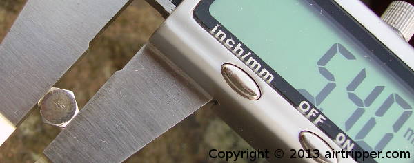
Measuring Hex Nut Or Bolt Head Diameter With Digital Calipers
I use to have to check this often when I include hex nut capture sockets in designs; the diameter measurements, used in OpenSCAD to make the hex shape socket, is taken from measuring flat edge to flat edge on the hex bolt head like the image above.
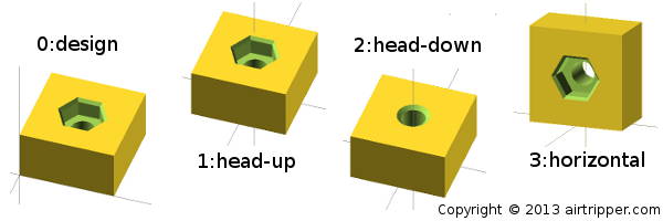
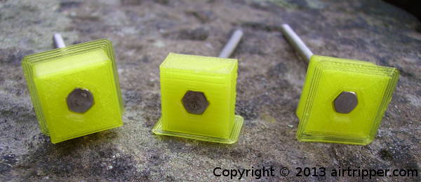
Hex Nut Capture Socket Rotation Options For 3D Printing
view_part = 1; // [0:design, 1:head_up, 2:head_down, 3:horizontal]
From my own tests I’ve found that the dimensions remained consistent after 3d printing the hex nut capture socket in different angles, and while the head-up and head-down provided the tightest screw head fits, the horizontal rotation was the cleanest fit and allowed the screw head to drop into position without force.
Use the view_part variable to select the model rotation options as shown above. Head_up, head-down and horizontal are centred ready for STL export for 3d printing while the design option shows the model in its original design position. Use the number assigned to each model for the variable view_part.
Hole Taper
As standard, the test part includes a taper at each end of the screw hole. The taper helps prevent the screw hole entrance from closing when first layer of plastic is pushed against the 3d printer build platform. I would recommend using tapers on screw holes, that face the build platform, for tight fitting screw head capture sockets.
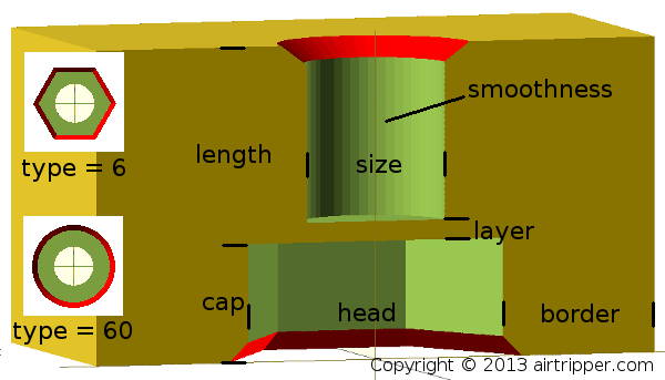
Hex Nut Model Configuration Variable Reference
// – Screw head diameter – flat side to flat side on hex nut or bolt head
head = 6.75;
// – Screw head type – [6] for hex head and [50] or more for round head
type = 60;
// – Screw size diameter
size = 3.65;
// – Screw size diameter smoothness
smoothness = 50;
// – Screw size length – not including screw head
length = 5;
// – Screw head length
cap = 3;
// – Block border thickness between screw head and block edge
border = 4;
// – Print layer thickness – only required for head down print
layer = 0.25;
Use the image above as a guide to the variable settings listed on the Thingiverse Customizer Application and in the OpenSCAD project file.
The layer variable is optional and it’s there to provide a platform for the screw hole when 3d printing the head_down rotation option. Assigning [0] to the layer variable will remove the platform. A layer height of 0.25 provided a strong enough support for M3 size screw shaft perimeters during printing tests; larger screw sizes may need a thicker platform.
The border variable should be a size big enough to fit all the perimeters and have a neat fill without leaving gaps.
Smoothness will need to be adjusted with the screw size diameter. A visual inspection of the 3d model will help determine the amount of smoothness needed. The smoothness variable only effects the hole for the threaded screw shaft. When using the type variable to adjust for a round head screw instead of a hex head, use the type variable for smoothing the screw head socket.
Hex Nut Capture Socket – Assemble
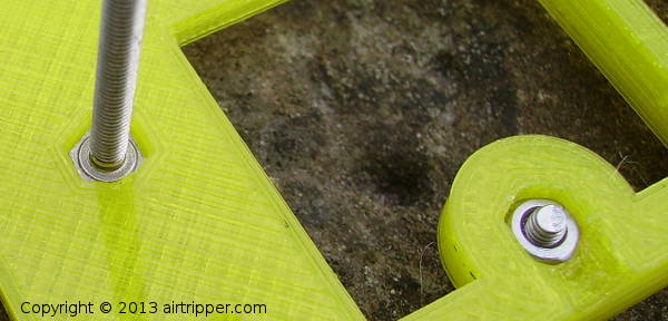
Arduino & Breadboard Rack Screw Fit Test
The settings found using the capture socket test part was able to successfully transfer to a finished project with the hex nuts and bolts fitting snugly.
The hex capture sockets can be a bit tight at first and can cause the bolt head to anchor on to the imperfections of the hex hole wall inside the socket. Unlike the hex nuts, the bolts hex head are rounded only on the top side and not on the bottom side. Plunging the bolt head first into the hex capture socket like in the picture above will help smooth out the hex hole to accept the bolt properly.
If you have used the layer variable to create a platform you will need a suitable size drill bit to punch hole through the screw hole once the part is printed.
Hex Nut Capture Socket – The Files
http://www.thingiverse.com/thing:153394
[bodyadsrich1l]
Related post that uses hex nuts and hex bolts in a project:
Airtripper Extruder Filament Force Sensor – Design & 3D Print
