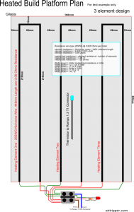
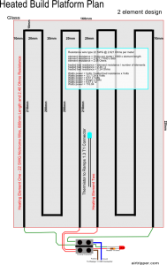
Resistance Wire Heated Build Platform, a few notes about my own heated build platform build for the SUMPOD and a tutorial for those who are looking to build their own. It’s quite a long piece because I have tried to make it as complete as possible. A couple of plans have been thrown in with some images to boot, which summarises much that have been written here, so a good place to start is with the images. I’ll be using the tutorial myself to improve the performance of my own heated build platform.
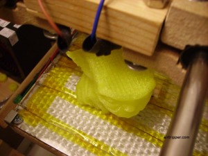
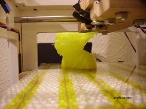
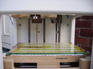 The notes will be about building a 3d printer heated build platform out of 3mm window glass and nichrome wire (resistance wire). This setup is ideal for printing PLA because it sticks to window glass without the need for any kind of tape, and PLA pops off the glass easily as the platform cools at the end of printing. Window glass is good for temperatures up to 80 degrees C which may not be hot enough for ABS printing. If ABS is how you roll then oven glass or ceramic glass may be a better option than window glass. The temperature I usually set, for printing with PLA filament, is between 55 degrees C and 60 degrees C.
Use the information at your own risk and do not leave the 3d printer unattended during operation because of risk of fire, safety first.
Resistance Wire Heated Build Platform Planning
Ohms and Watts
To build the heated build platform we need to figure out a few things first so that we can get the right bits together. We know that the RAMPS 1.3 board (RepRap Arduino Mega Pololu Shield) recommends a power supply be rated for at least 11 Amps to supply the heated build platform, that will give us a starting point to work out the lowest total desired resistance for the heating elements combined. The calculations will be based on 12v power supply that is rated to supply more than 11 Amps of current. So from that we can work out the total minimum resistance we need for our heating element by dividing the power supply voltage by the maximum amount of current we want to draw. I’m going to use 11 Amps as a guide to calculate the minimum resistance we want for the heated build platform, anymore than that will overheat the RAMPS 1.3 board. So we can calculate that 12 Volts divided by 11 Amps will give us a resistance value of 1.09 Ohms. Calculating power = 12 Volts x 11 Amps will give us 132 Watts of power which should provide a fast heat bed warm up, the lower the power rating, the longer it will take for the resistance wire heated build platform to reach the target temperature.
Now that we know what the minimum desired resistance we want for our heated build platform, we now want to work out the maximum desired resistance. This is important because we need to know what margin of resistance is acceptable when working out the design of the heating elements. The wider the resistance margin the easier it is to design the heating elements. We want the heated build platform to reach the target temperature quickly so we will work out the maximum resistance that will give us at least a 100 Watts heated build platform. So, Amps = 100 Watts divided by 12 Volts will give us 8.33 Amps, and Ohms = 12 Volts divided by 8.33 Amps will give us 1.44 Ohms resistance. Now we have a resistance margin to work with, which will be between 1.09 and 1.44 Ohms.
Our target resistance is set within the resistance margin we have defined above, which is the resistance of all the heating elements combined built into the heated build platform. If the heated build platform requires two heating elements then each element needs to have a resistance two times that of the target resistance, so if the target is 1.5 Ohms then each element should have a resistance of 3 Ohms. Each heating element should have a resistance of the target resistance times the number heating elements used in the heated build platform.
Target Resistance = Element Resistance / Number of Elements
Element Design
One way to design the resistance wire heating elements for the heated build platform is to use a vector graphics editor like a free to download program like Inkscape from inkscape.org, or you could use paper, pencil and ruler. The idea is to sketch the heat bed outline and the resistance wire heating element design to scale so that the glass can be placed on top of it for tracing the resistance wire around the element design.
Depending on the size of the heated build platform you are working on, you may need more than one resistance wire heating element and ideally, you want all the heating elements resistance wire ends to finish at the same end off the platform. Also you want to decide which end of the platform you want the electrical wires to lead off and route to the electronics and enough wire slack will be needed for axis motion.
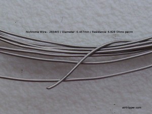
Designing a heating element with one continuous resistance wire to cover the whole heated build platform may be possible, but the resistance wire required, will be far too thick to work with and keep it stuck down. I would recommend using a resistance wire of 22 gauge and up for easier usability, a table of resistance wire gauges is shown below with corresponding resistance values per meter.
Nichrome Wire / Resistance wire table
| Gauge (SWG) | Diameter (mm) | Resistance (Ohms) |
| 18 | 1.219 | 0.9596 |
| 20 | 0.914 | 1.707 |
| 22 | 0.711 | 2.821 |
| 24 | 0.559 | 4.563 |
| 26 | 0.457 | 6.828 |
| 28 | 0.376 | 10.09 |
| 30 | 0.315 | 14.37 |
| 32 | 0.274 | 18.99 |
A single heating element is one continuous resistance wire that is spread across the whole of the heated build platform or spread across a portion of it, in which case, more than one heating element is used to heat the bed, with all the resistance wire elements being the same length and pattern. Glass is a good thermal insulator so it is important to make sure the resistance wire is spread across it as evenly as possible to avoid cold spots during heating. Uneven heating may result in the glass cracking or breaking and could cause issues with 3d print’s bond to the heated build platform during printing because of wide temperature differences and changes.
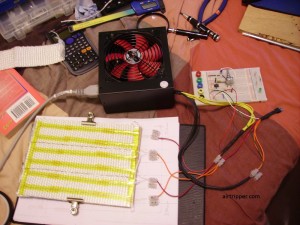
When designing a resistance wire heating element for 3mm window glass, I would recommend having the resistance wire no more than 20mm apart down the length of the glass and also have the resistance wire placed with a gap from the edge of the glass measured less than half the gap of that measured between resistance wires. I’ve included images as an example of what a heated build platform plan could look like which includes some calculations to work out the ratings.
Choosing the resistance wire
It is a lot easier to match a resistance wire to the desired plan we want for our heated build platform because it gives us more flexibility in creating the desired heating element pattern. If you have the resistance wire already, you’re plan options are going to be limited.
Unless your heated build platform is a lot smaller than mine, I would recommend starting with at least two heating elements. It is just a case of sketching out the first heating element to cover half the platform to get a rough idea of the length of resistance wire we need for one heating element. Assuming we are going to use two heating elements in our plan, each element needs to be twice the target resistance to fit within the resistance margin calculated earlier which is between 1.09 and 1.44 Ohms. So if our heating element resistance wire is 880mm in length we can select a resistance wire from the list and divide it’s resistance by 1000 and times it by 880 and then divide by 2 to see if the result meets our target resistance range. If you tested the 22 SWG resistance wire from the list in the calculation, it will be found to be the best match and this would be the resistance wire or nichrome wire to buy for the heated build platform. If you needed 3 elements at 880mm in length then the 24 SWG resistance wire will be the best match having calculated resistance = resistance per meter / 1000 x 880 / 3 elements.
Bits you may need
Nichrome wire – or resistance wire, a wide range of gauges can be found on ebay. Should be easy enough to find any of those in the list above.
Glass – Window glass has been used successfully by me and other people, just keep the temperature below 80 C and you should be fine. If you can get heat resistant glass then even better, but can’t be sure if PLA sticks to this type directly, in which case, tape may need to be used. 3mm window glass is used for this tutorial project.
Power supply – for example if using the Ramps 1.3 board to power the printer and the heated build platform, you will need a power supply capable of supplying at least 16 Amps. A modded PC power supply can be used and may be the cheapest option.
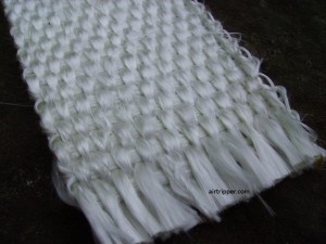
Exhaust wrap – This can be used to insulate the underside of the glass and help keep the kapton tape stuck down on the glass that’s holding the resistance wire in place. This can be found on ebay but shop around because prices can be a large difference between suppliers.
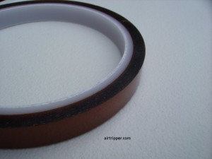
Kapton tape – If you’re already into 3d printing, then you may have this already but again, available from ebay. A roll 10mm in width is the one I used for my heated build platform.
Blu-Tack – This is good for holding down the resistance wire onto the glass while forming the heating element.
Electrical wire – Two sorts of wire may be needed, suitable wire to connect each end of the resistance wire to a terminal block and suitable wire to connect the terminal block to the Ramps board, each type of wire needs to have a power rating better than what was calculated for the heating element or heated build platform.
Terminal block – May be needed to connect all the wires from the heating elements, use one with at least a 15 Amp rating.
Thermistor – Refer to the RepRap Wiki for more information which covers the types recommended for use with your 3d printer firmware. A suitable connector will be required to fit the board like the RAMPS 1.3. The thermistor I used is one from rapidonline.com part no. 61-0452, Gt Thermistor 100k 3%.
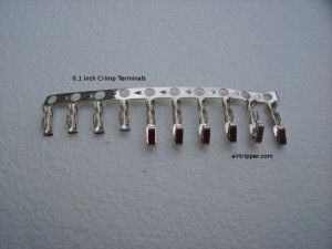
Crimp connectors – or bootlace ferrules to join the electrical wire to resistance wire, solder may not stick to resistance wire but soldering the crimped join should make a more robust connection which is needed for a moving heated build platform. Solder may not be useful on resistance wire connections for higher bed temperatures due to the low solder melt point.
Heat shrink tubing – Some of this will be recommended for use to install the thermistor, it would help to reduce the possibility of the thermistor wires shorting.
Acetone – or nail polish remover, the type without added oil, is used to clean the heated glass bed if printing PLA plastic directly on to it. Dirty or greasy heated glass bed will prevent PLA sticking to it.
Heated Build Platform Assembling
So, you have all the the bits and ready to start building your heated build platform for your 3d printer. To build the heated build platform, follow the steps below:
Getting ready. If you are using a transparent glass platform and you have made a resistance wire heated bed plan like the above, then you just start with placing the glass platform onto the plan. Next, cut the resistance wire to length to match the length decided on the plan, and if using more than one heating element, cut all the resistance wires to the same length so that they all have the same resistance.
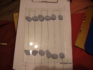
Shaping the resistance wire. Before you attempt to make the resistance wire heating element, roll up a few small balls of Blu-Tack ready to tack down the resistance wire onto the glass. Place the resistance wire onto the glass and first tack down the ends of the wire where the heating element begins and ends at the edge of the glass. Now form the rest of the heating element by working towards the middle starting from the ends of the resistance wire. Keeping the wire u-turns rounded during the heating element forming will allow you to make adjustments to the pattern easily to best fit the heating element plan placed under the glass.
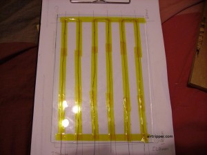
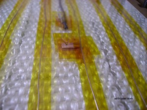
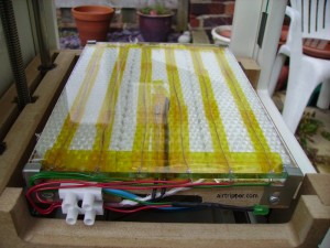
Sticking it down. Once you have all the heating elements in place and applied the finishing touches, the heating element is ready to be stuck down with Kapton tape. Kapton tape the resistance wire to the glass, first between the Blu-Tack, then fill the gaps with Kapton tape after removing the Blu-Tack. Leave a bit of the resistance wire ends bare so that they can be connected to electrical wire.
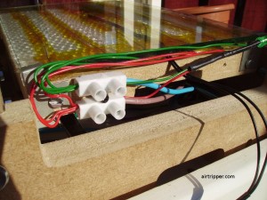
Connecting the wires. How the electrical wires are going to fit will depend on the 3d printer design. Place the heated bed in the 3d printer, to help decide what wire lengths are needed, and plan the electrical wire routes from there. Remove the heated bed from the printer to attach the electrical wires to the resistance wires. Some of the images included will show an example of how the electrical wires might be connected up. I used 0.1 inch crimp terminals to connect electrical wires to resistance wires but bootlace ferrules can be used as well. Make sure the connections are robust enough to cope with heated build platform axis motion.
Adding the thermistor. Prepare the thermistor to be stuck on the glass by connecting electrical wire to it’s legs using bootlace ferrules or some other clamping type of connector. Insulate the bare wires up to the thermistor bead with Kapton tape to avoid shorting, also use shrink tubing where necessary. For best thermistor placement checkout the post Heated Build Platform Rework, stick the thermistor to the glass with Kapton tape.
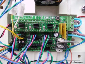
Fitting to 3d printer. Fit the glass bed on to the printer and connect all the wires. For best heat bed performance and to protect the 3d printer, add a thermal barrier to the glass underside. Route the thermistor wire and the heated build platform wire to the control board. Fit a connector to the thermistor wire if required and connect to the control board. If using the RAMPS 1.3 board, the thermistor would be connected to header pins labelled T1, while the heated build platform would be connected to D8 connector. Attach the power supply, to feed both the 5 Amp and the 11 Amp connectors in the case of the RAMPS 1.3 board.
Final checks. Check that all the wires are securely connected and check that axis motion does not trap any of the wires. Make sure that one end of each heating element is connected to ground while the other end of each heating element is connect to +12 Volts. Disconnect the heated build platform from the control board and test the resistance of the platform with a multimeter to see if it meets within our target margin resistance. If no resistance is detected then there could be a short circuit or no electrical circuit and will need to check the wires again.
Resistance Wire Heated Build Platform Testing
Once you are happy with the resistance wire heated build platform installation and all the electrical wires are connected correctly and securely, then the next step is testing.
Before the heated build platform and thermistor can work they need to be enabled in the control board firmware, but before you do that, test that the printer is functioning normally with the new power supply if you changed it. Now that you know the power supply is working, update the firmware on the control board to enable the heated build platform and thermistor. With the 3d printer powered up and connected to interface software, confirm a proper reading is being made from the thermistor, about ambient temperature, and if that looks OK, test the resistance wire heated build platform starting at a low temperature first and increase from there until you reach your desired target temperature. An infrared thermometer would be useful to compare the bed temperature with the thermistor reading.
Adding a heartbeat. An LED can be added to the resistance wire heated build platform, as shown in some of the images, to show that the heated bed is live. Just add a 1k Ohms resistor to the longest leg (anode) of the LED and add extra wire to the LED legs to the desired length. The wires and the resistor can be connected to the LED with bootlace ferrules without soldering. Use heatshrink tube or insulation tape to insulate the wires. Connect the LED leg with the 1k resistor to 12v and connect the other leg to ground, the LED is connected to the electrical wire that is connected to the resistance wire from the control board.
Closing. Thanks for your interest in this tutorial and hope it was useful. If you managed to build a resistance wire heated build platform from the notes, please leave a comment.
[bodyadsrich1l]

I’ve build my own heated bed with resistance wire.
Is it ok if the wire glows because it gets so hot? Does your wire glow?
Hi,
The resistance wire should not glow, at least for the 3d printer build platform anyway. You might have miss-calculated the resistance and ended up with the resistance being too low across the resistance wire.
You will need to check you are using the intended wire gauge. Check that the resistance was calculated correctly for each length of wire. Was the resistance divided correctly, if using more than one length of resistance wire.
Mark
Hi Mark
Are you still using this bed design? Would you change anything on it?
Hi,
I’ve been using the same nichrome wire heated build bed almost two years now without any maintenance apart from the occasional bed levelling. I only use PLA filament at the moment so window glass has been ideal due to the PLA filament sticking to it; and the nichrome wire set-up has worked great.
Now knowing more about window glass thermal properties I probably would add more resistance wire to the glass if I had to build the heated build platform again. The resistance wire layout as it is now can have more than 5 degrees Celsius variance across the glass surface.
I may use oven glass on the next heated build platform design so I can get the temperature up higher for other filament material types, and then just add a plate of window glass on top whenever I use PLA filament for 3d prints.
Mark
Do you have to use glass? Could you use something more thermally conductive and use less power to get the plate to temperature?
Glass (window) is chosen because PLA material sticks directly very well too it. Also, glass is not electrically conductive, which means bare resistance wire can be used safely without risk of shorting.
Using another type of build surface might mean having to prepare the surface between each printing session. However, if using plastic other than PLA, this will be the case anyway.
A more thermally conductive platform would be of metal type, and this will not work safely using resistance wire as the heating element, it is unlikely it will create much power saving over glass. The best way to reduce power, is to reduce the size of the heated build platform.
Mark
thanks for getting back so quick! have you looked into printing on borosilicate glass (like pyrex)? that way you’d get over the temperature restrictions of window glass you were talking about?
I’m looking at using borosilicate in the future. People have talked about sandblasting the surface to improve bonding to plastic; I’ll probably just add a layer off window glass on top when printing PLA.
I’m hoping borosilicate will work as a hot plate for surface mount soldering, it’s a project I’ve got lined up.
Pingback: Beginning Work on Custom 3d Printer – Heated Print Bed | Hobbies of a Bogue Rat